Speaker
Ideation
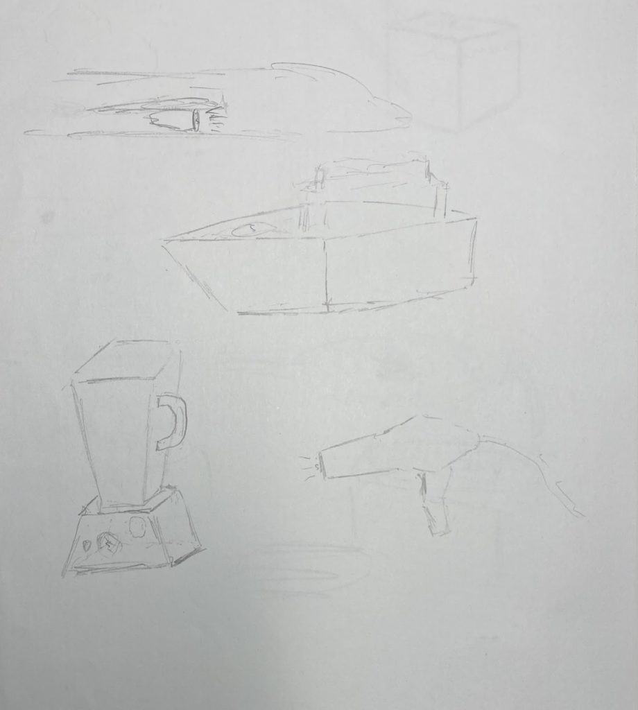
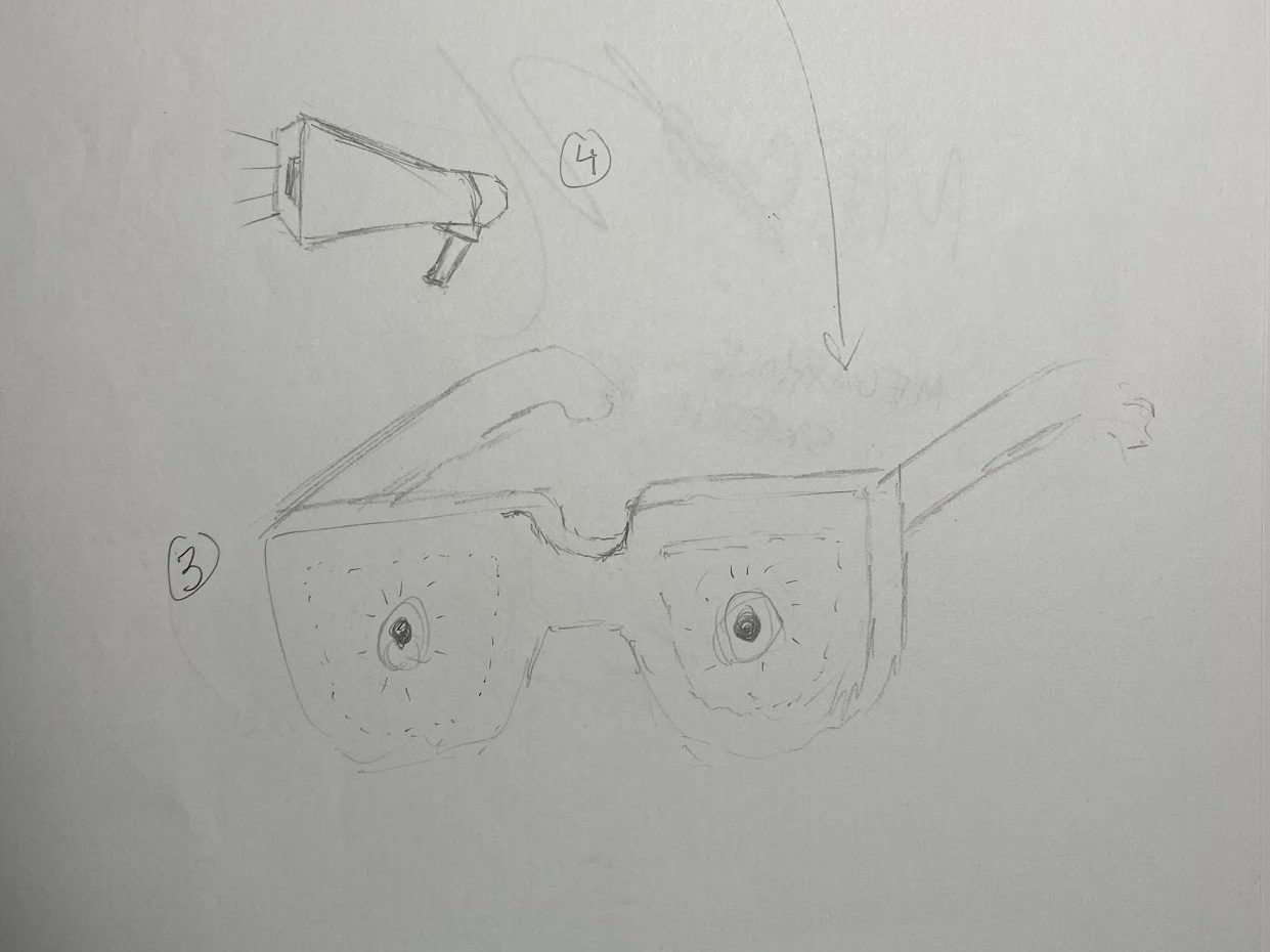
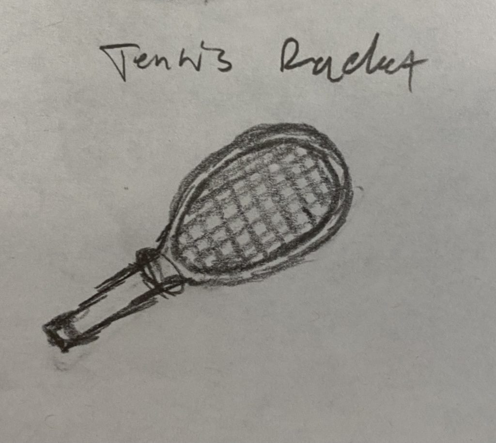
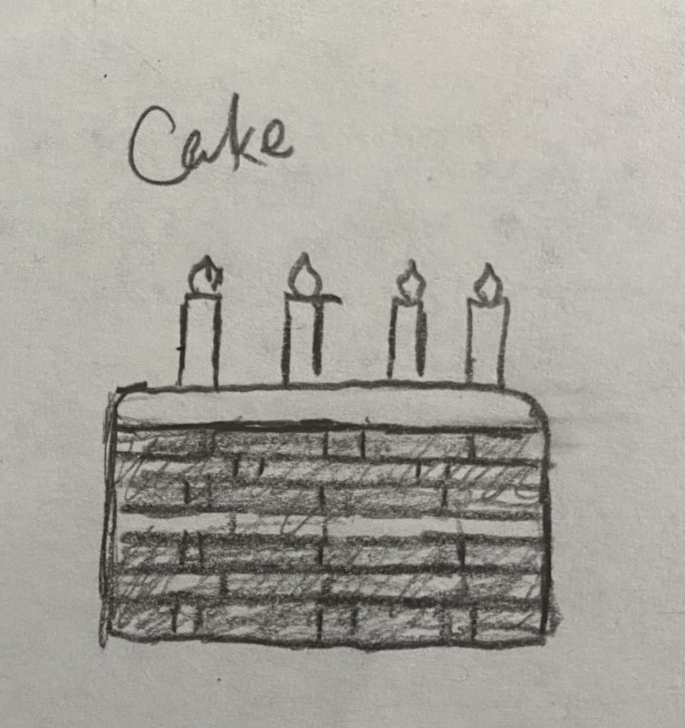
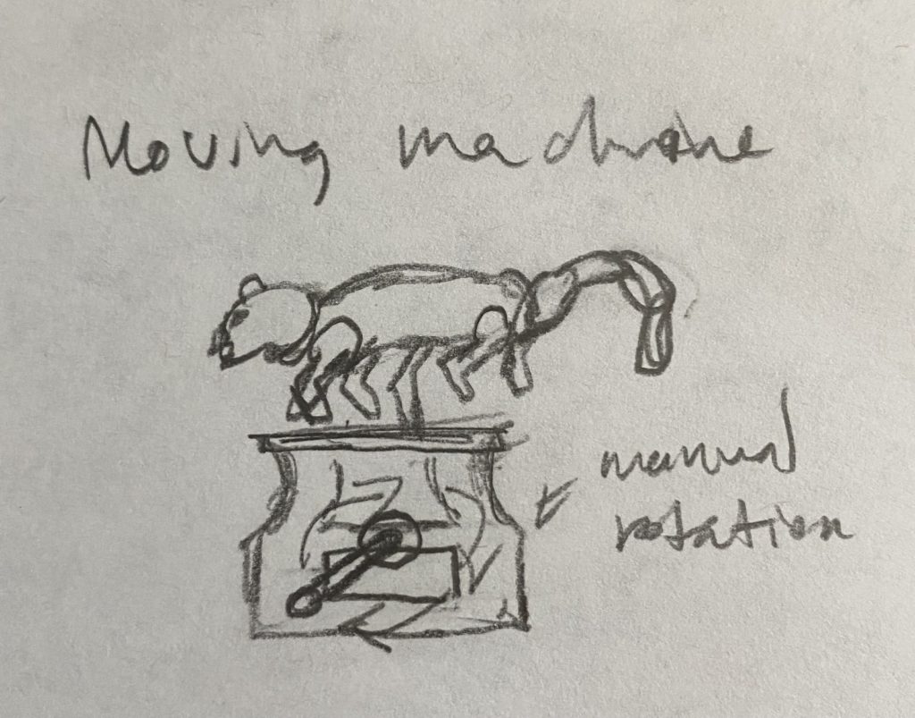
These are some speaker ideas drawn in a bit more detail:
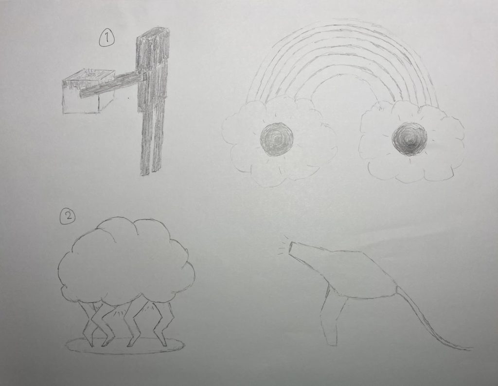
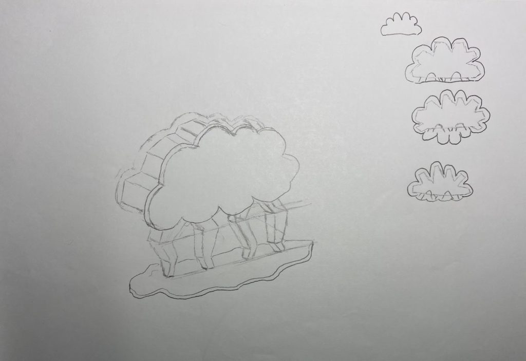
After some feedback from peers, and fleshing out my ideas a bit more, I settled on this cloud design below. In the middle is a 3D-ish drawing of the speaker and on the right are a couple different ways the cloud and inside of the cloud could look like.
Modeling
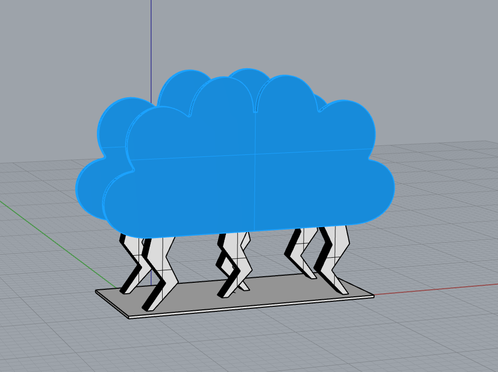
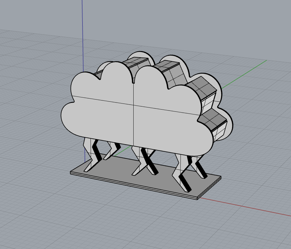
This is my basic amplifier design in Rhino. I still want to rework the cloud a bit to have better or more curves, the shape of the bottom plate, and add the wood pieces between the cloud plates:
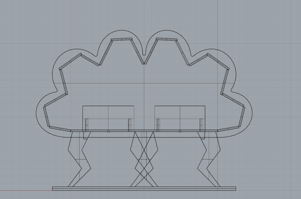
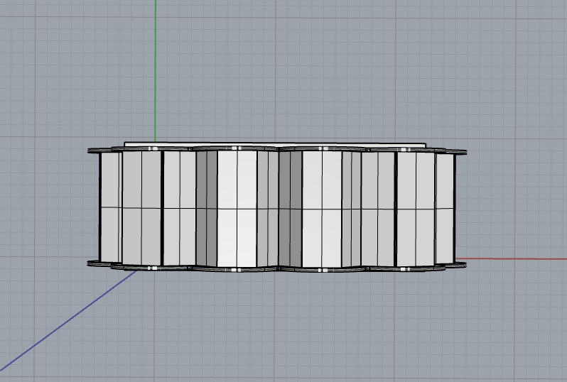
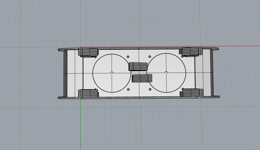
This is my final design in Rhino. I added pieces between the clouds to connect the two, and cut out speaker holes:
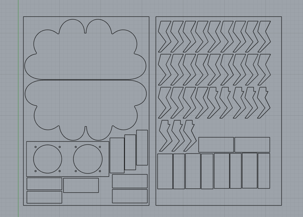
This is my flat layout with all the speaker pieces reading for cutting:
Prototyping
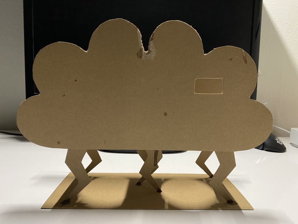
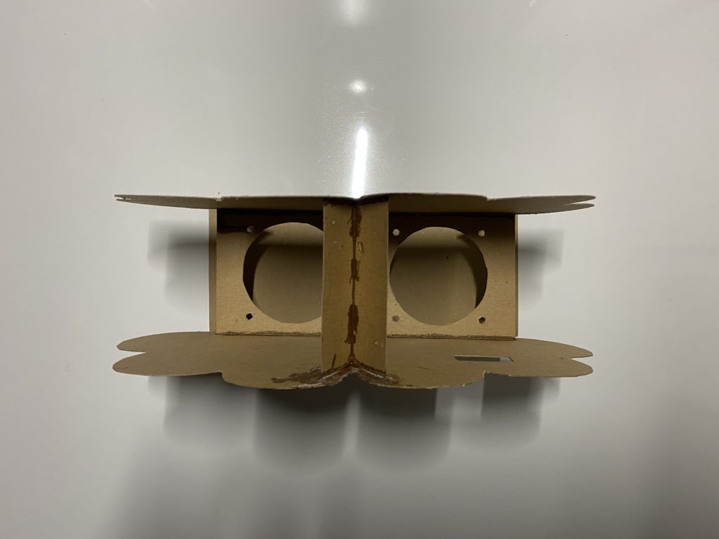
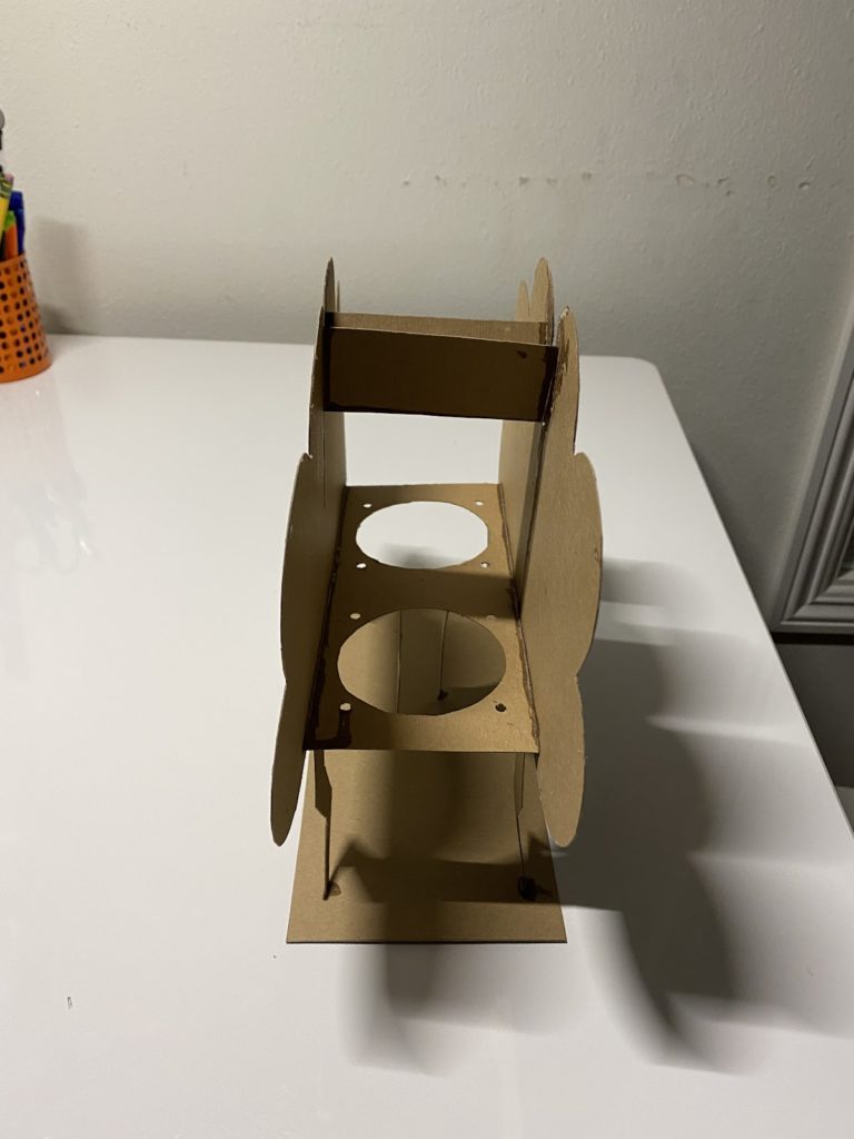
To better visualize my design, I created a to-scale prototype using cardstock. I used super glue to connect all the pieces together, so in some spots, some of the material is ripped due to it sticking to my table, and there is some glue dripping from some areas. Here are some photos:
Electronics
Breadboard
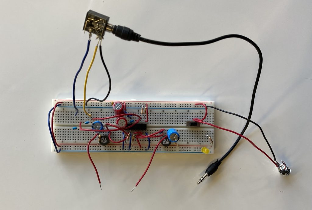
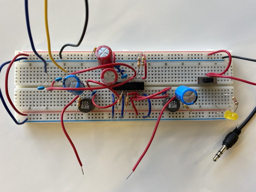
The first step of wiring up my amplifier was placing and connecting the parts on a breadboard and getting the speakers working. Here is the finished breadboard circuit:
Eagle
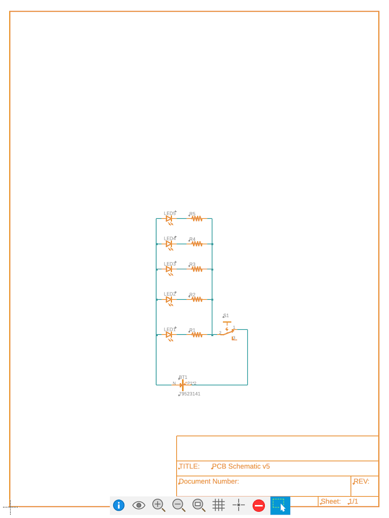
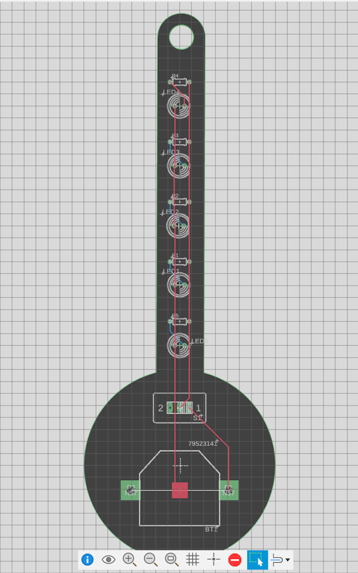
This is what my PCB looks like in Eagle, the left being the schematic and the right being the board
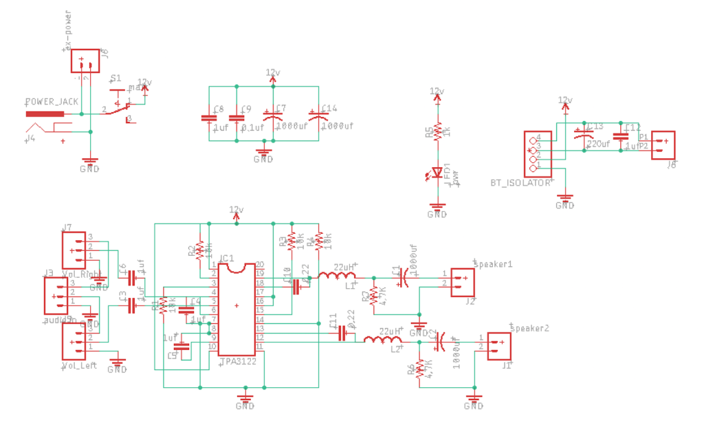
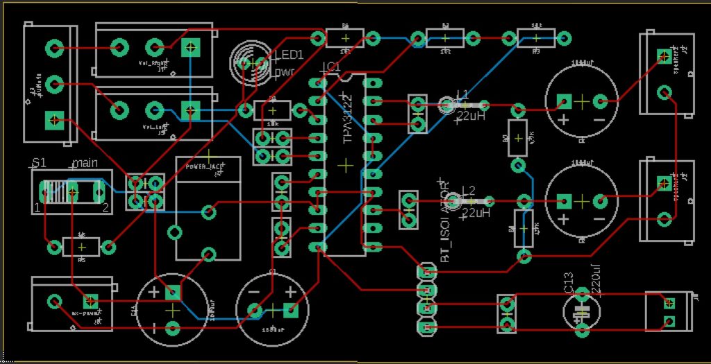
I wish I had rounded the corners of the board, so it wouldn’t be sharp on the edges.
Printed Circuit Board
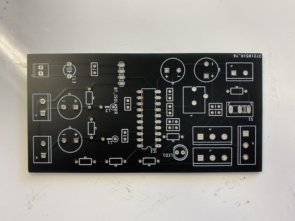
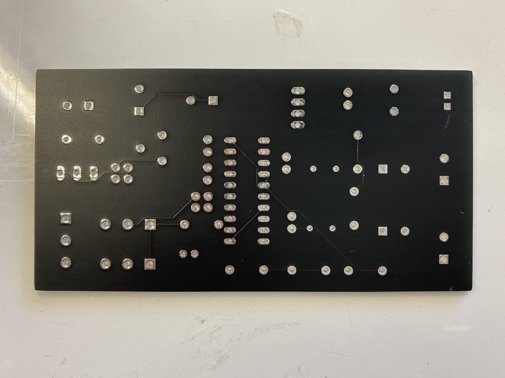
This is what the board looked like before any components were added, front and back:
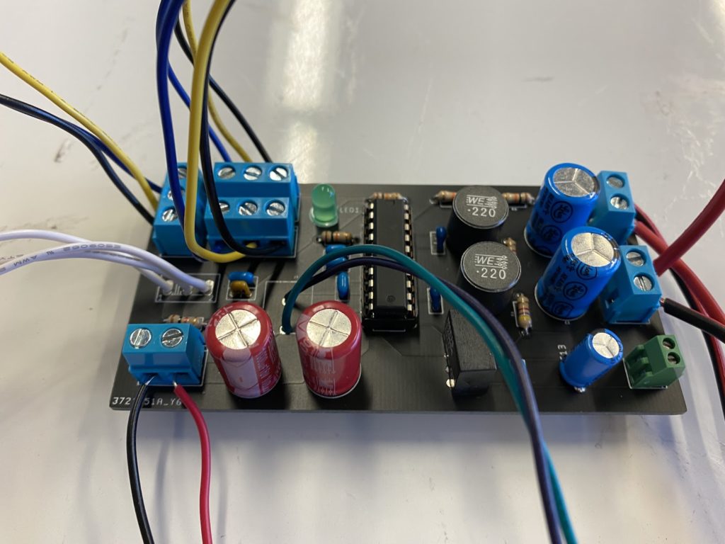
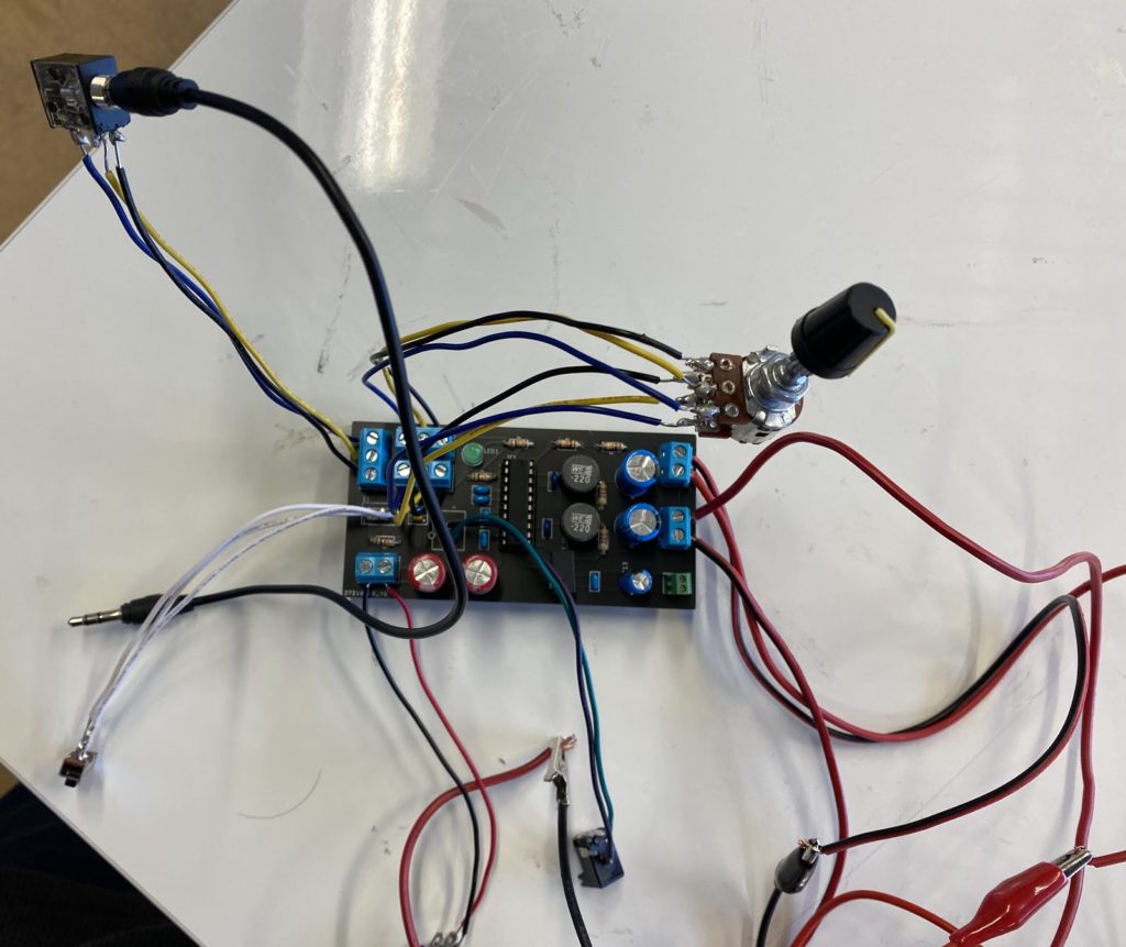
This is what the board looked like after all components were added:
Coding
Code Experimentation
This is some modified example code for an OLED screen. I changed the text to an interesting Shakespeare quote I found to play around with.
# SPDX-FileCopyrightText: 2021 ladyada for Adafruit Industries
# SPDX-License-Identifier: Unlicense

import board
import time
import displayio
import terminalio

# can try import bitmap_label below for alternative
from adafruit_display_text import label
import adafruit_displayio_sh1107

displayio.release_displays()
# oled_reset = board.D9

# Use for I2C
i2c = board.I2C()
display_bus = displayio.I2CDisplay(i2c, device_address=0x3C)

# SH1107 is vertically oriented 64x128
WIDTH = 128
HEIGHT = 64
BORDER = 2

display = adafruit_displayio_sh1107.SH1107(display_bus, width=WIDTH, height=HEIGHT)

# Make the display context
splash = displayio.Group()
display.show(splash)

while True:
    my_text = "Away,"    #add your text here
    text_area2 = label.Label(
    terminalio.FONT, text=my_text, scale=4, color=0xFFFFFF, x=13, y=30
    )
    splash.append(text_area2)   #add your text to splash

    display.show(splash)   #anything that is in splash will show on the screen
    time.sleep(1)
    splash.pop(-1)    #remove the last item added to splash

    my_text = "you"   #add some next text
    text_area2 = label.Label(
    terminalio.FONT, text=my_text, scale=4, color=0xFFFFFF, x=6, y=30
    )
    splash.append(text_area2) #add your text to splash

    display.show(splash)    #anything that is in splash will show on the screen
    time.sleep(0.3)
    splash.pop(-1)    #remove the last item added to splash

    my_text = "three"   #add some next text
    text_area2 = label.Label(
    terminalio.FONT, text=my_text, scale=4, color=0xFFFFFF, x=6, y=30
    )
    splash.append(text_area2) #add your text to splash

    display.show(splash)    #anything that is in splash will show on the screen
    time.sleep(0.3)
    splash.pop(-1)    #remove the last item added to splash

    my_text = "inch"   #add some next text
    text_area2 = label.Label(
    terminalio.FONT, text=my_text, scale=4, color=0xFFFFFF, x=6, y=30
    )
    splash.append(text_area2) #add your text to splash

    display.show(splash)    #anything that is in splash will show on the screen
    time.sleep(0.3)
    splash.pop(-1)    #remove the last item added to splash

    my_text = "fool!"   #add some next text
    text_area2 = label.Label(
    terminalio.FONT, text=my_text, scale=4, color=0xFFFFFF, x=6, y=30
    )
    splash.append(text_area2) #add your text to splash

    display.show(splash)    #anything that is in splash will show on the screen
    time.sleep(1.5)
    splash.pop(-1)    #remove the last item added to splash

    my_text = "I"  #add some next text
    text_area2 = label.Label(
    terminalio.FONT, text=my_text, scale=4, color=0xFFFFFF, x=6, y=30
    )
    splash.append(text_area2) #add your text to splash

    display.show(splash)    #anything that is in splash will show on the screen
    time.sleep(0.5)
    splash.pop(-1)    #remove the last item added to splash

    my_text = "am"   #add some next text
    text_area2 = label.Label(
    terminalio.FONT, text=my_text, scale=4, color=0xFFFFFF, x=6, y=30
    )
    splash.append(text_area2) #add your text to splash

    display.show(splash)    #anything that is in splash will show on the screen
    time.sleep(0.5)
    splash.pop(-1)    #remove the last item added to splash

    my_text = "no"   #add some next text
    text_area2 = label.Label(
    terminalio.FONT, text=my_text, scale=4, color=0xFFFFFF, x=6, y=30
    )
    splash.append(text_area2) #add your text to splash

    display.show(splash)    #anything that is in splash will show on the screen
    time.sleep(0.5)
    splash.pop(-1)    #remove the last item added to splash

    my_text = "beast."   #add some next text
    text_area2 = label.Label(
    terminalio.FONT, text=my_text, scale=4, color=0xFFFFFF, x=6, y=30
    )
    splash.append(text_area2) #add your text to splash

    display.show(splash)    #anything that is in splash will show on the screen
    time.sleep(2)
    splash.pop(-1)    #remove the last item added to splash
Digital Project
After starting a new program and taking bits and pieces from what I played around with, I created a simple time displaying program with the Real Time Clock module. I still want to add more to it like displaying the day of the week and date, but I haven’t had enough time to get to that yet.
# importing libraries
import board
import time
import busio
import displayio
import terminalio
import adafruit_pcf8523

from adafruit_display_text import label
import adafruit_displayio_sh1107

displayio.release_displays()

# activating I2C, display and rtc
i2c = board.I2C()
display_bus = displayio.I2CDisplay(i2c, device_address=0x3C)
rtc = adafruit_pcf8523.PCF8523(i2c)

# setting rtc time
rtc.datetime = time.struct_time((2021, 12, 16, 0, 53, 45, 4, -1, -1))

#adding screen dimensions
w = 128
h = 64

display = adafruit_displayio_sh1107.SH1107(display_bus, width=w, height=h)

# setting up display
onscreen = displayio.Group()
display.show(onscreen)

while True:
    actualhour = rtc.datetime.tm_hour # variable for hour of the day
    actualM = 0 # variable for AM or PM - 0 is AM, 1 is PM
    if 13 <= actualhour <= 23:
        actualhour = actualhour - 12
        actualM = 1
    elif actualhour == 12:
        actualM = 1
    elif actualhour == 0:
        actualhour = 12
        actualM = 0
    if len(str(actualhour)) <= 1: # makes writing time better looking
        actualhour = "0" + str(actualhour)
    actualmin = rtc.datetime.tm_min # variable for minute of the day
    if len(str(actualmin)) <= 1: # makes writing time better looking
        actualmin = "0" + str(actualmin)
    actualsec = rtc.datetime.tm_sec # variable for second of the day
    if len(str(actualsec)) <= 1: # makes writing time better looking
        actualsec = "0" + str(actualsec)
    actualtime = str(actualhour)+":"+str(actualmin)+":"+str(actualsec)
    if actualM == 0:
        actualtime = str(actualtime) + " AM"
    if actualM == 1:
        actualtime = str(actualtime) + " PM"

    # prints time for testing purposes
    print(actualtime)

    itext = actualtime   #add your text here
    dtext = label.Label(terminalio.FONT, text=itext, scale=1, color=0xFFFFFF, x=30, y=31)
    onscreen.append(dtext)   # adds items for display

    display.show(onscreen)   # displays list items
    time.sleep(1)
    onscreen.pop(-1)    # removes the last item from screen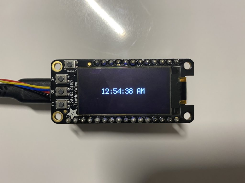
This is what it looks like when running, and every second it updates the time then displays the new time. It also switches between AM and PM, displaying 12 hour time.
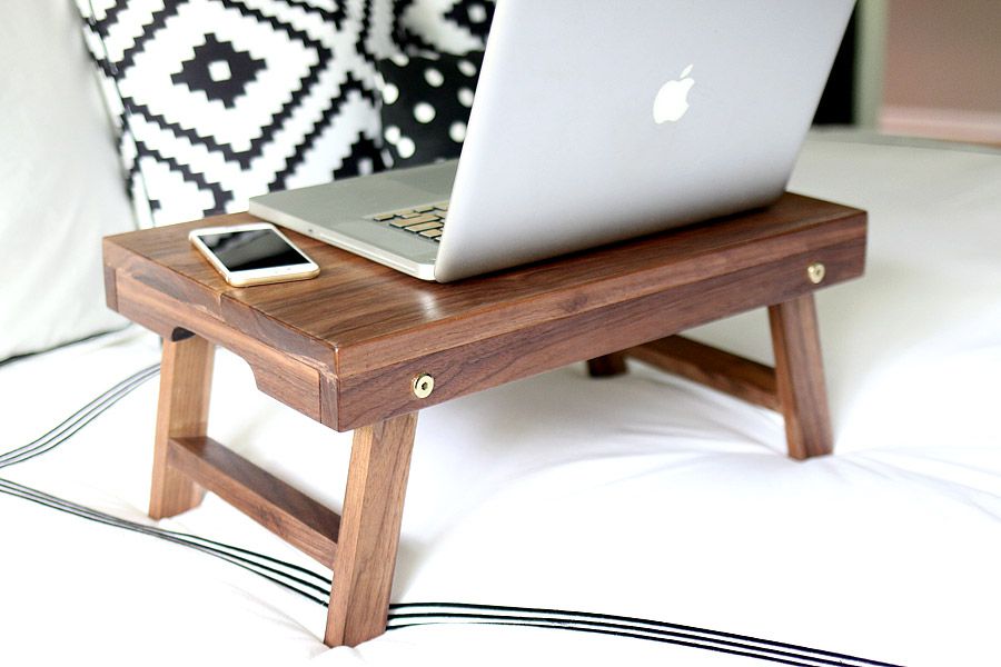
Final Build
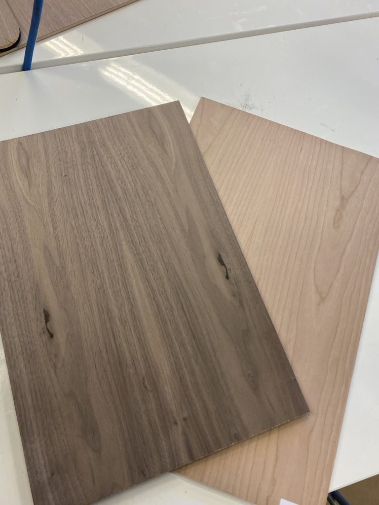
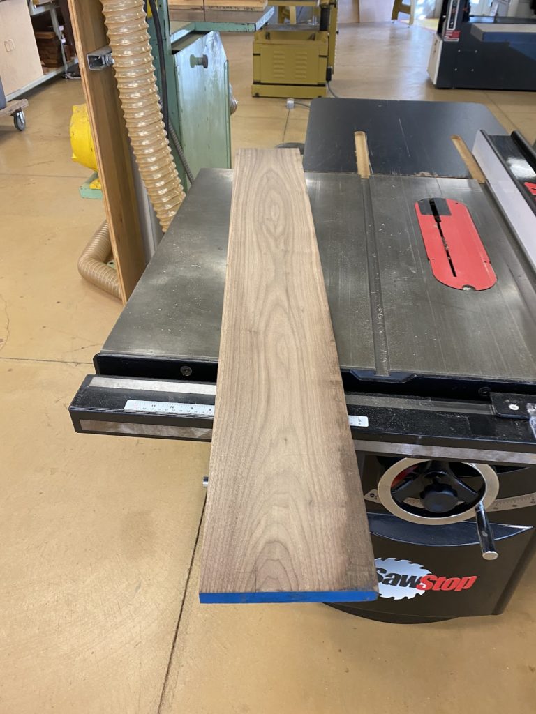
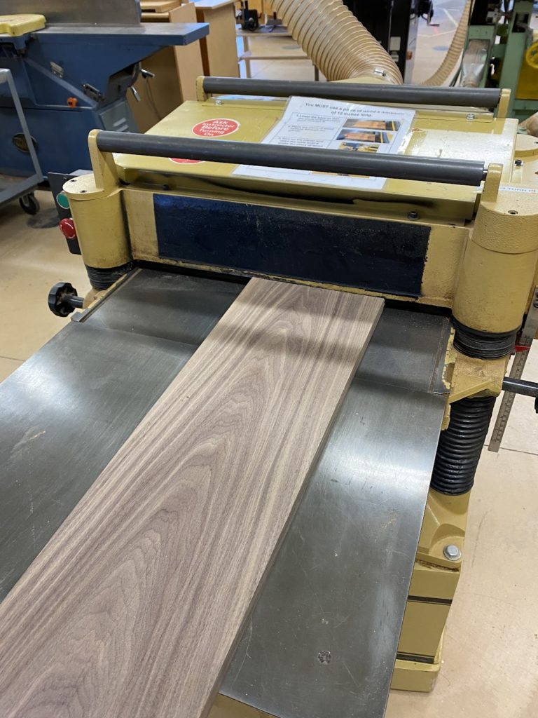
I chose the Walnut 1/4″ Veneer and Cherry 1/4″ Veneer. This is what they look like before cutting.
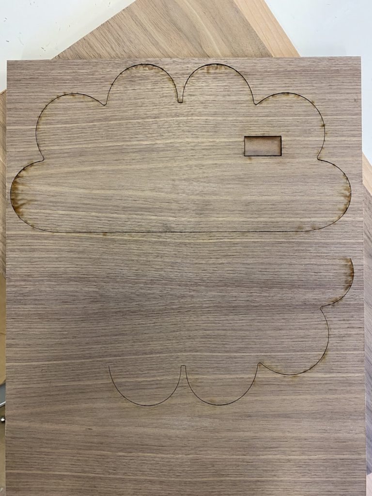
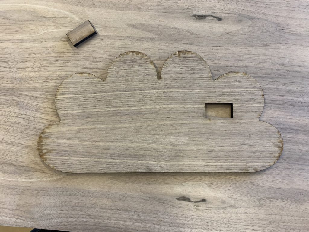
This is what the front cloud piece ended up looking like. It’s not included in my screenshots of my Rhino design because it was a last minute addition, but the square hole in the cloud is for my OLED screen.
Drawers
Ideation
Initial design ideas/moodboard
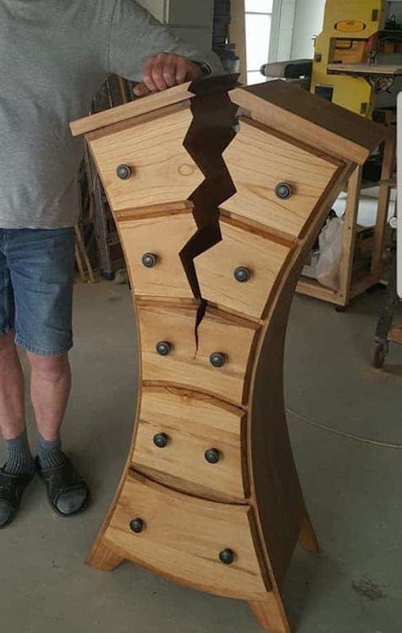
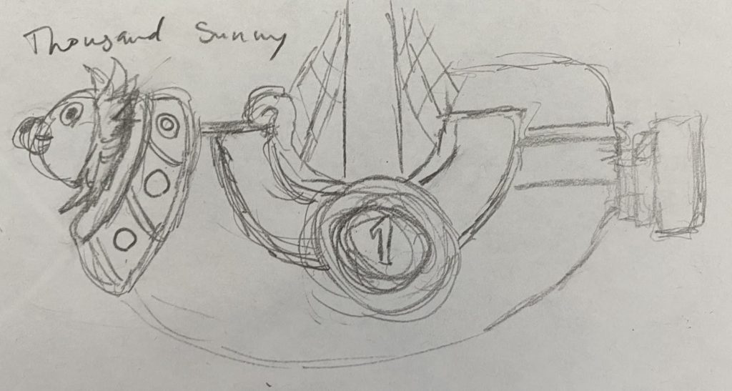
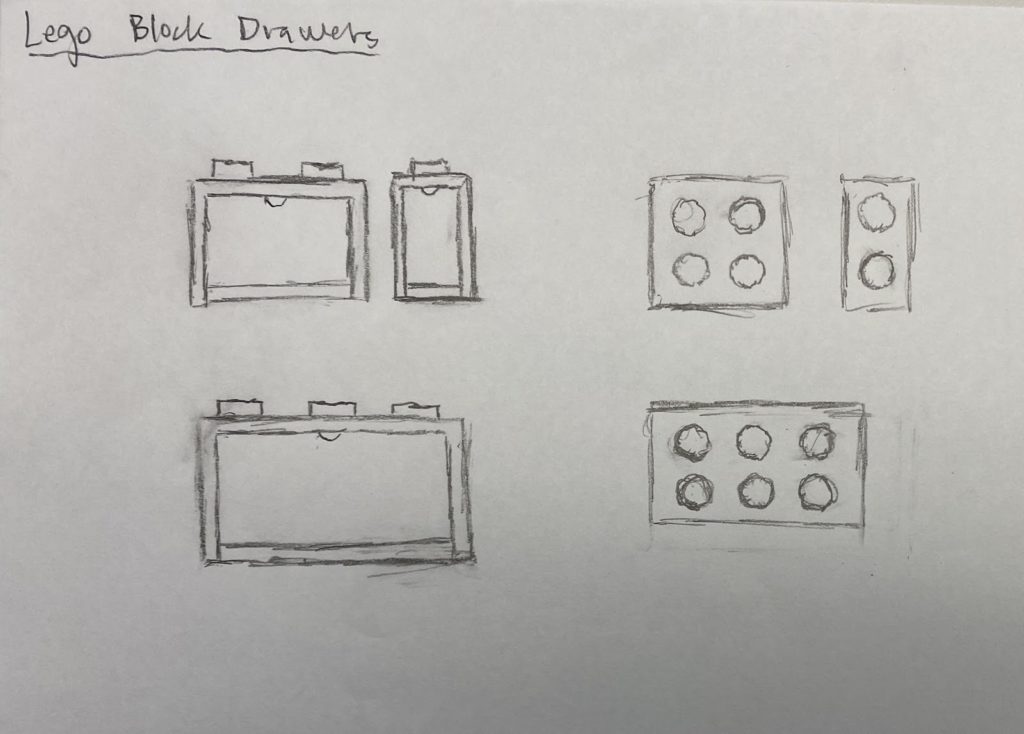
Hand sketches of initial designs:
Final Design
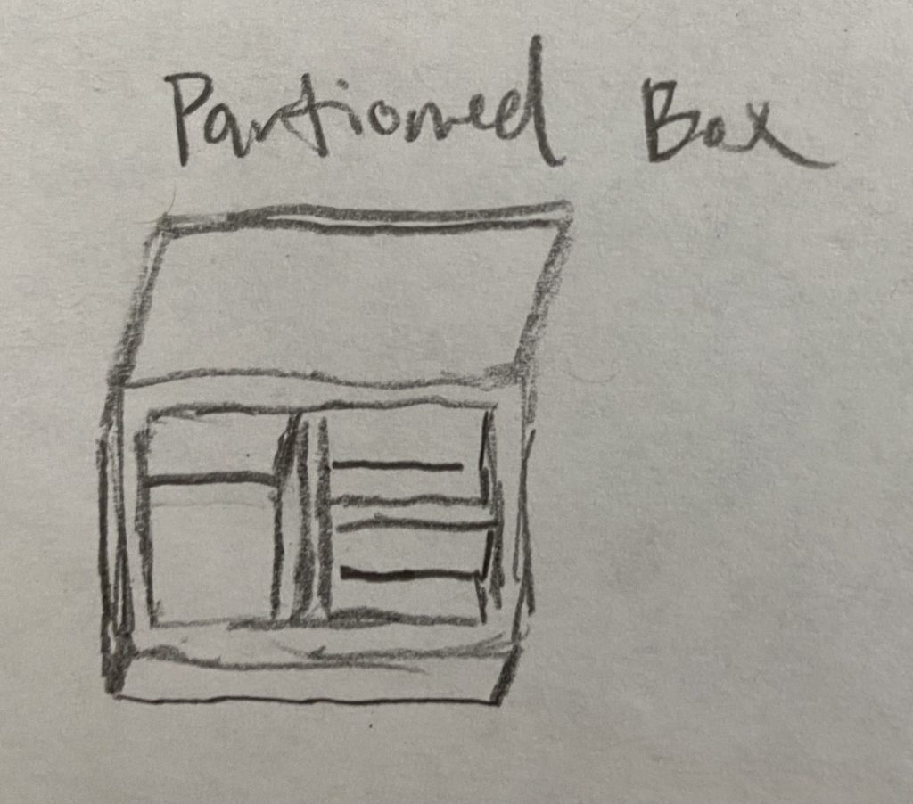
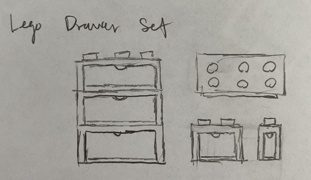
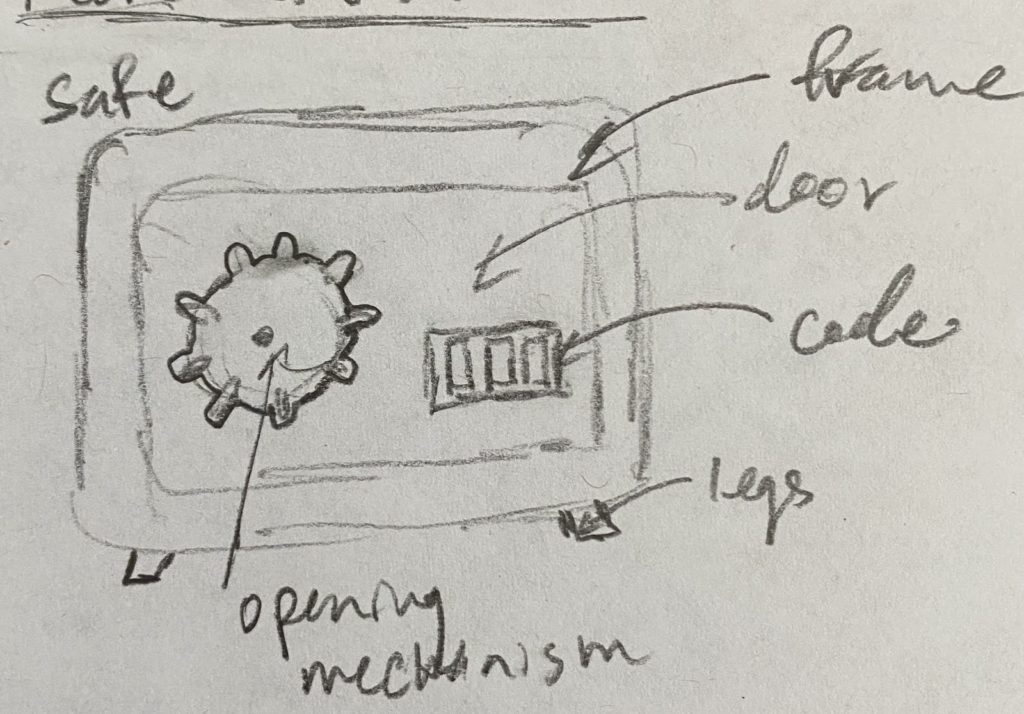
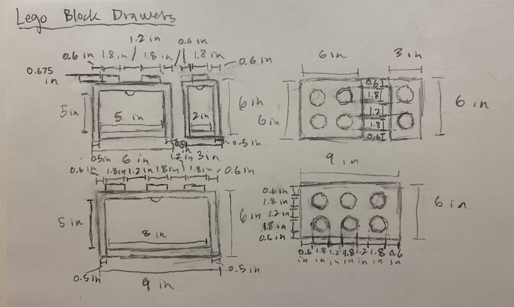
More detailed sketches of my final design:
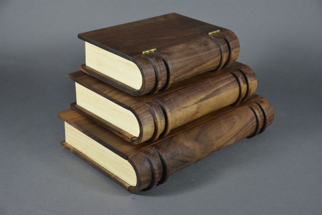
Fabrication
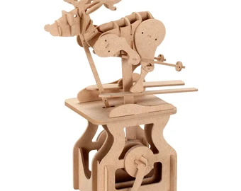
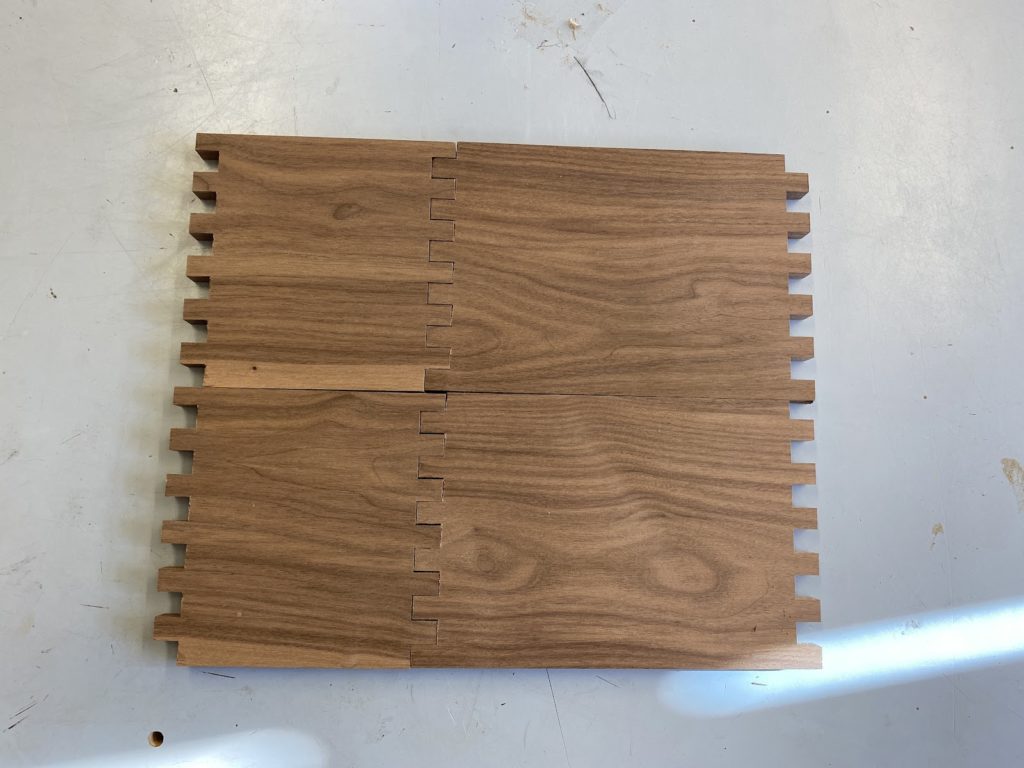
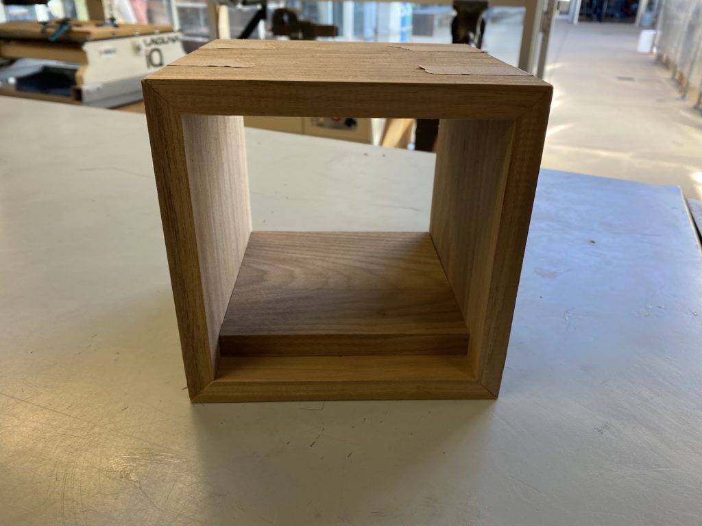
Finger Joint Practice – I first created a prototype with finger joints to practice with tools before creating my real project:
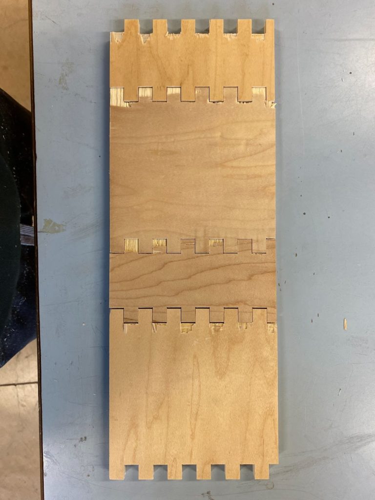
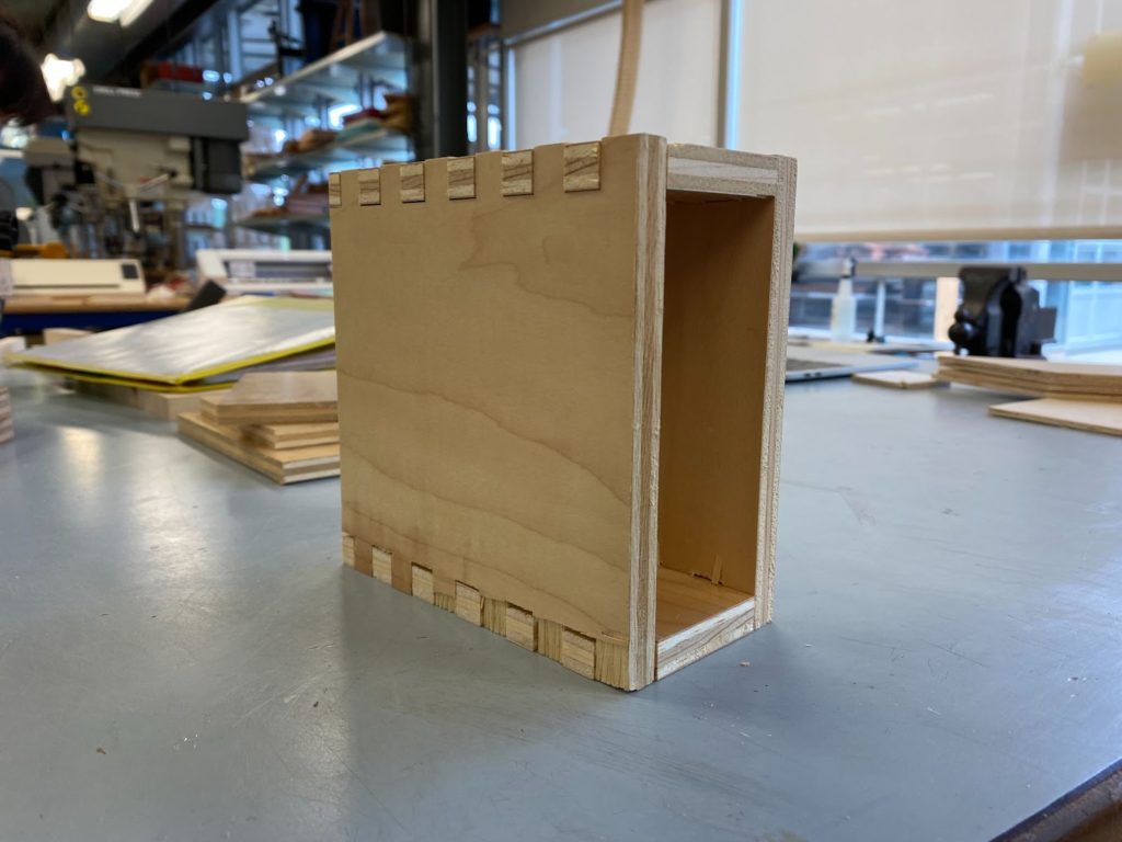
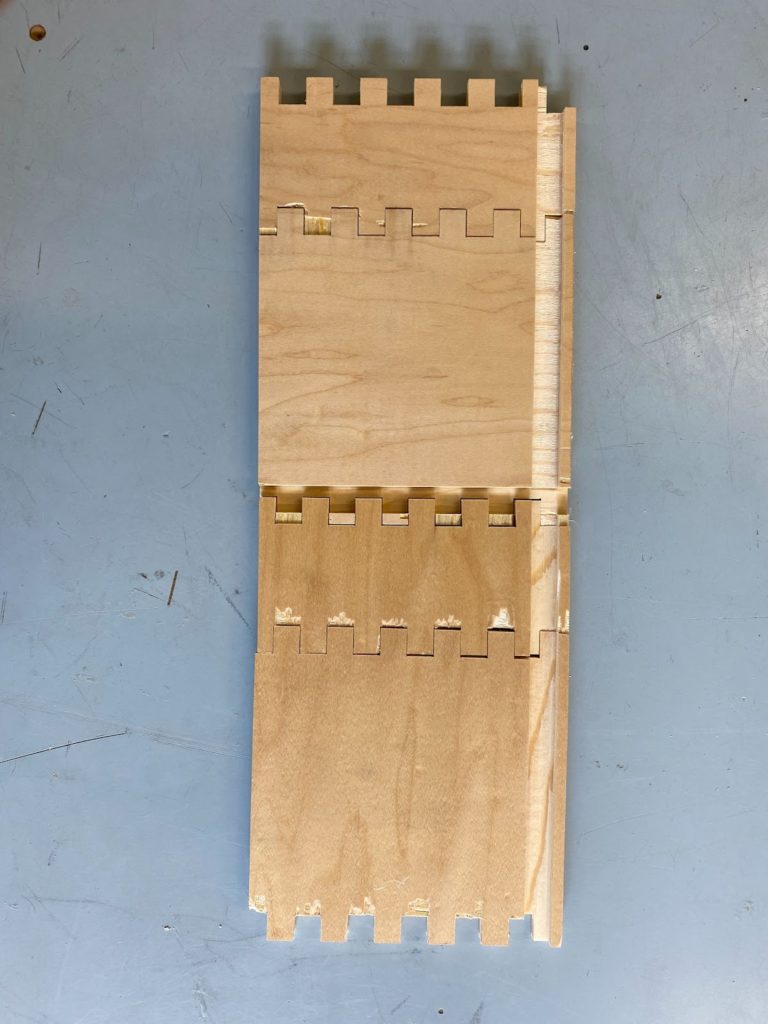
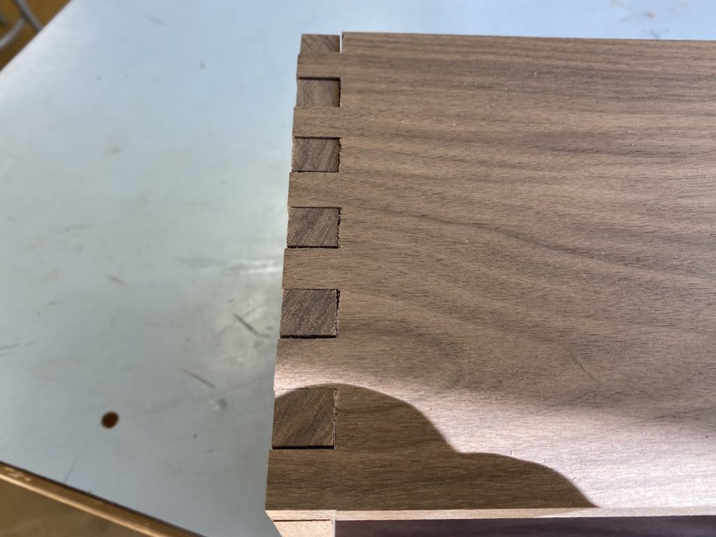
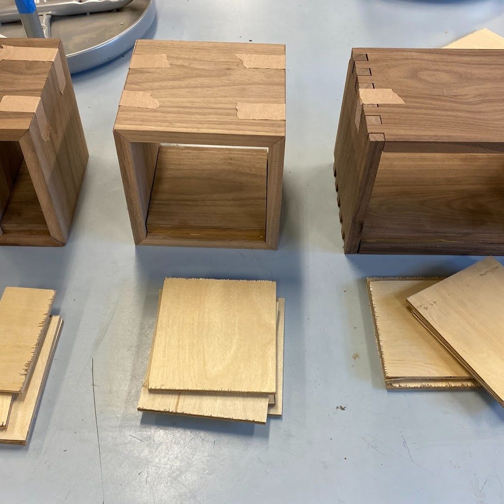
Finger jointing (real drawers):

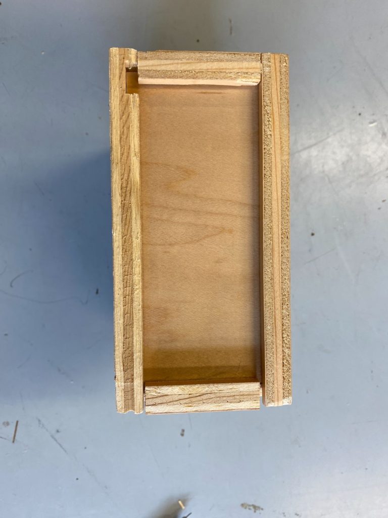
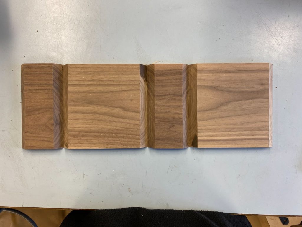
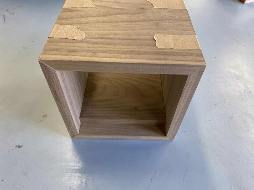
Smaller drawer frame fabrication (tried mitering instead of finger joints):
CNC Cutting:
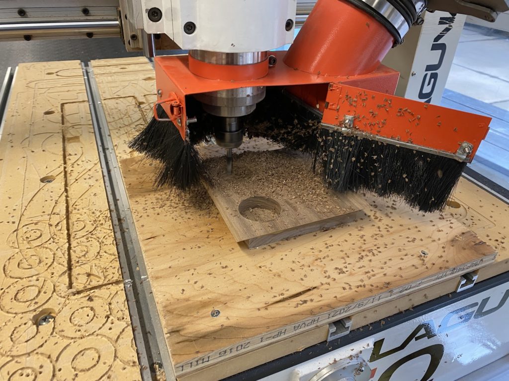
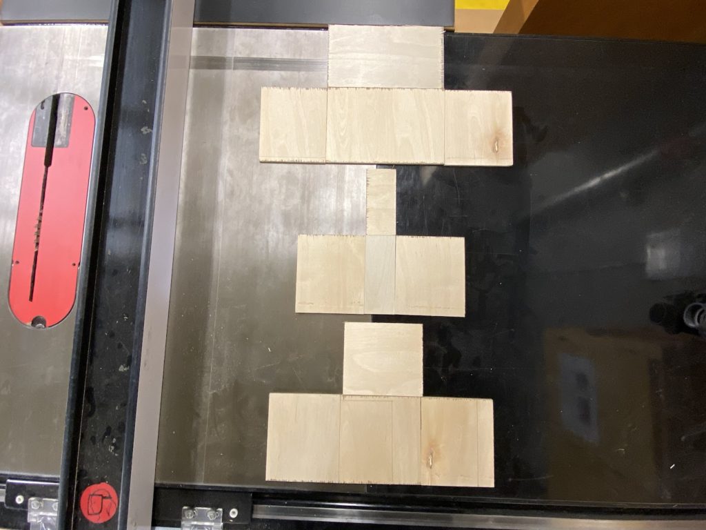
CNC cutting setup: I screwed a rectangle piece of plywood parallel and into the CNC bed. I then used very strong double sided tape on the smaller wood plates to attach the wood pieces firmly to the plywood, still parallel to the edge of the CNC bed, and centered my cuts on the center point of my wood.
Drawing Fabrication
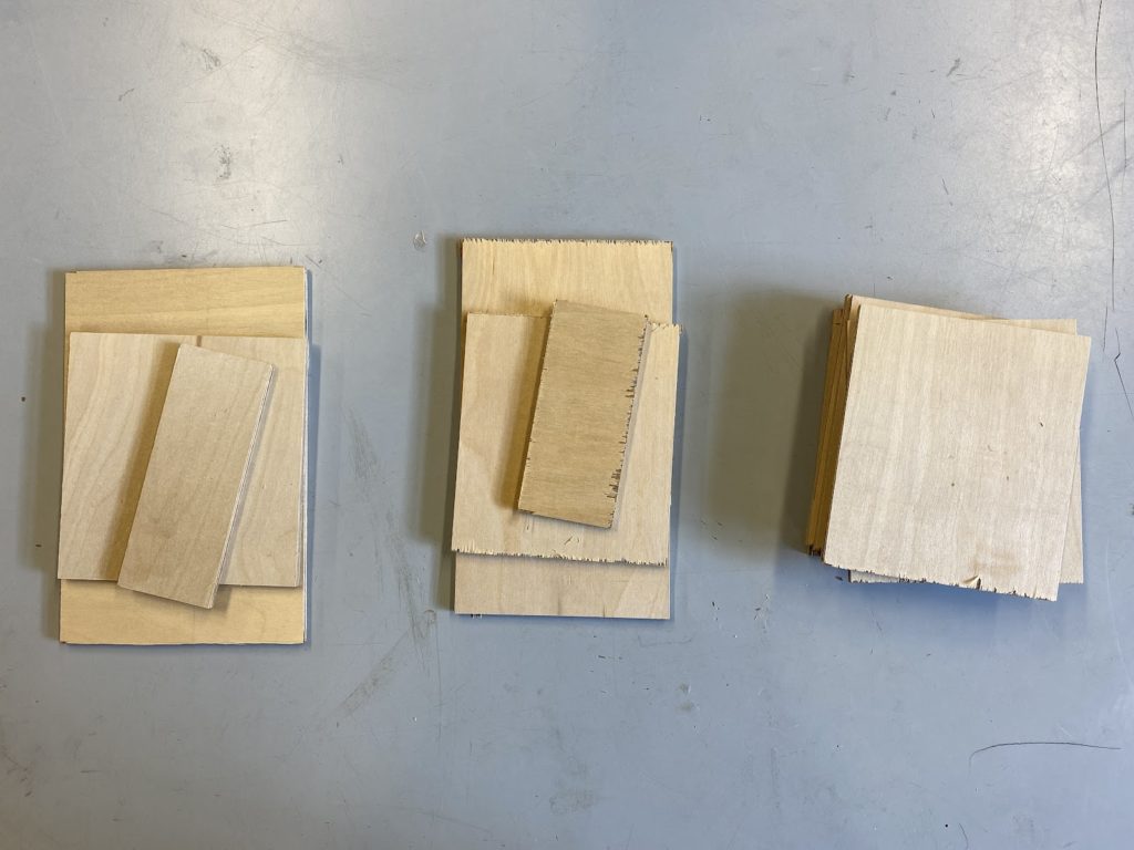
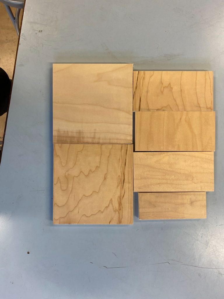
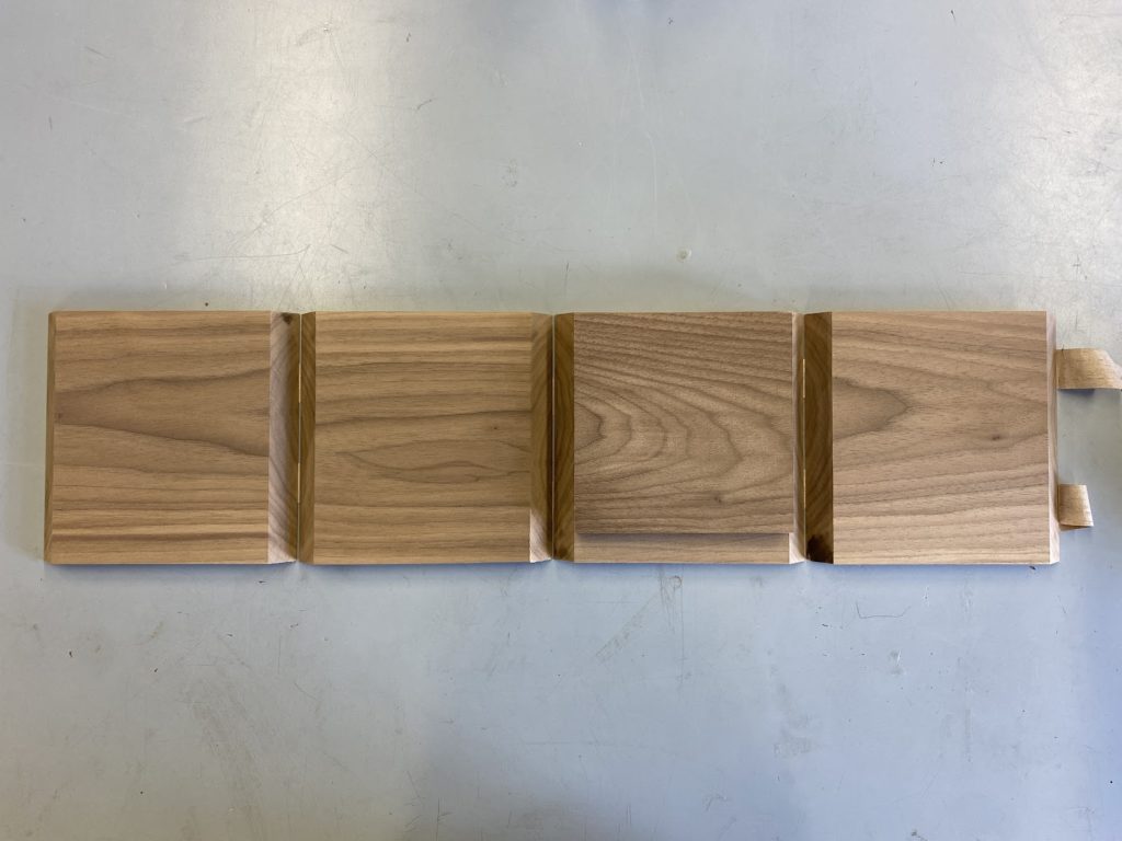
I started with a big sheet of 1/4 inch plywood (top left image) and cut it into drawer sides and bottoms (on the top right image–bottoms on the left, backs in the middle, sides on the right). To the left are the 2D layouts of all the small pieces.
Parametrically-Designed Light Fixtures
Ideation
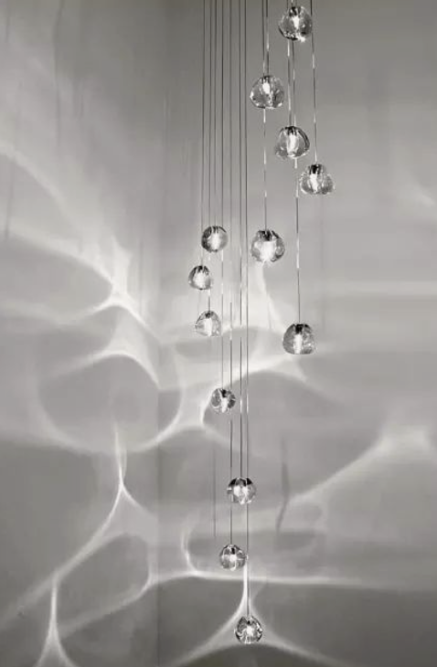
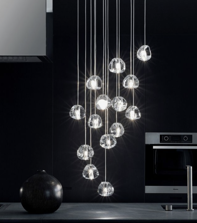
These are some examples of what we were aiming for in our design:
Design
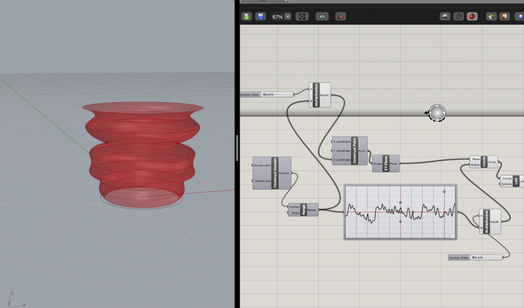
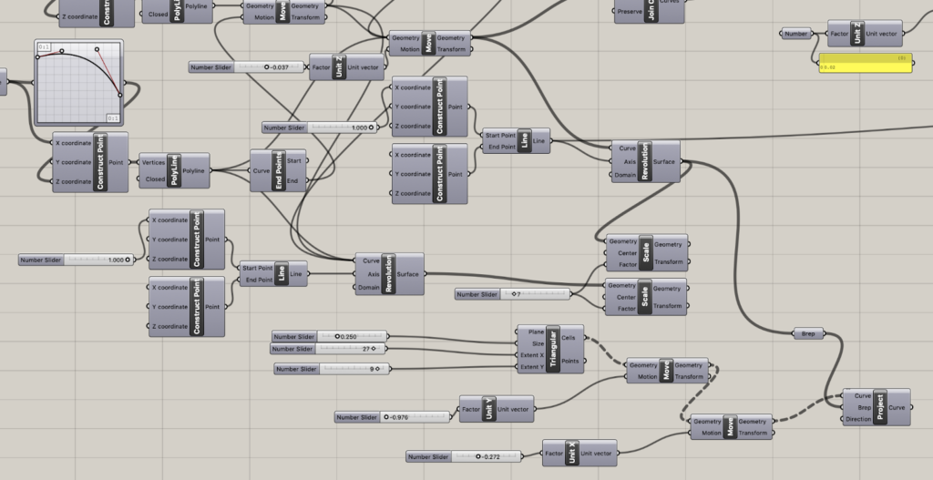
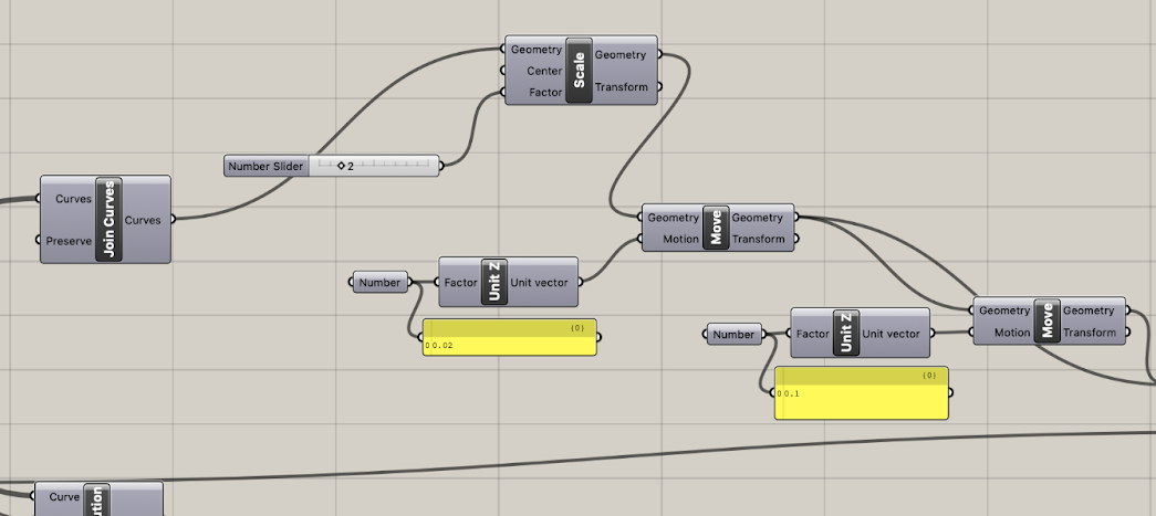
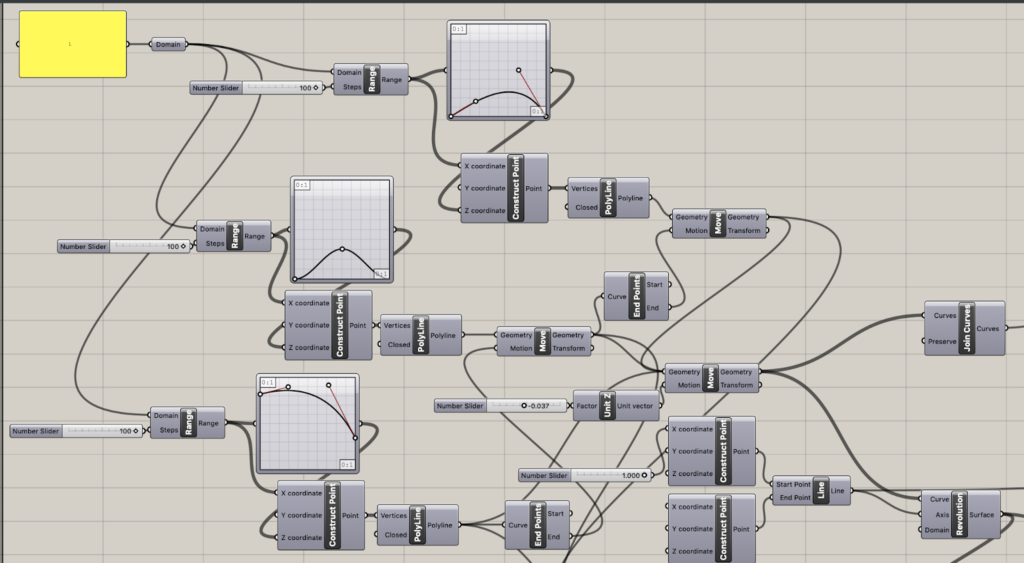
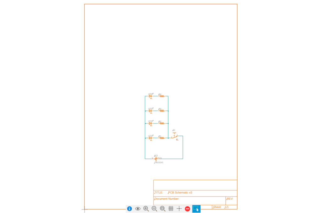
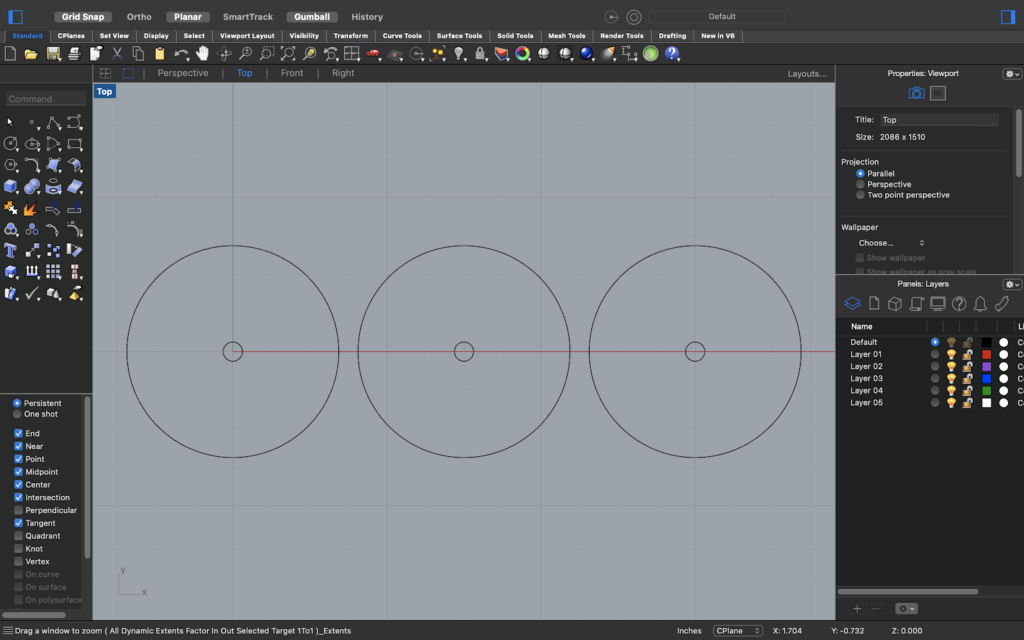
Final grasshopper scripts:
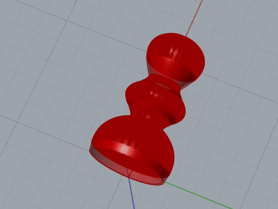
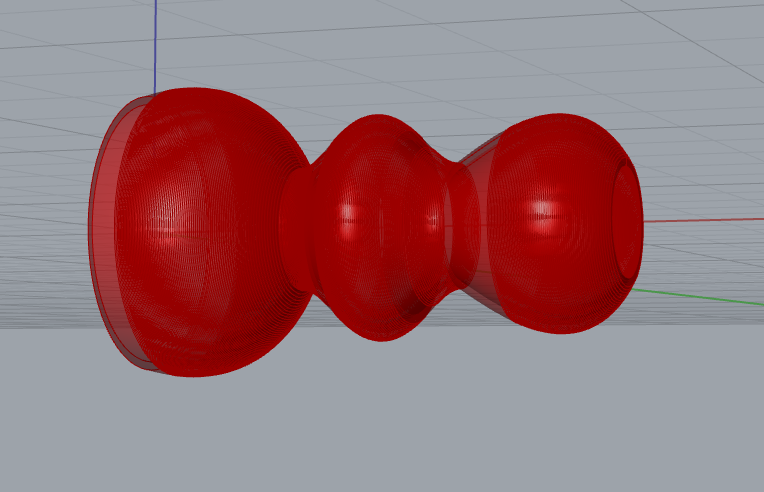
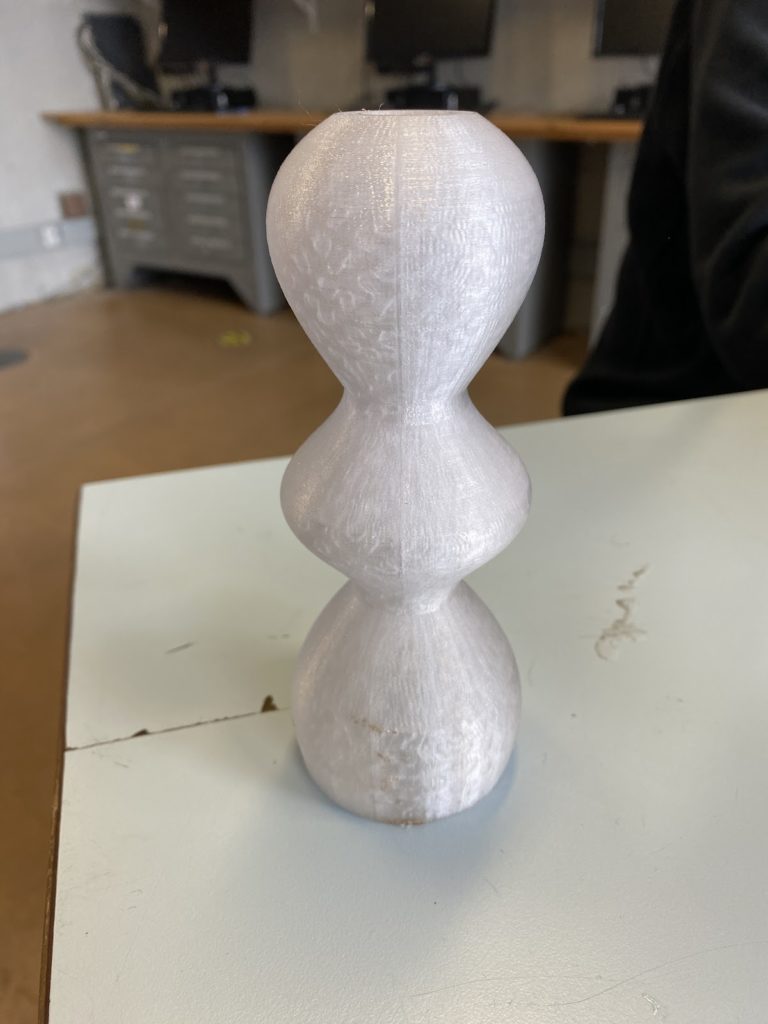
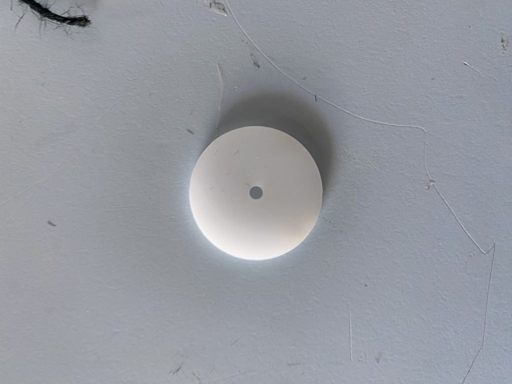
Resulting 3D model of our light fixture:
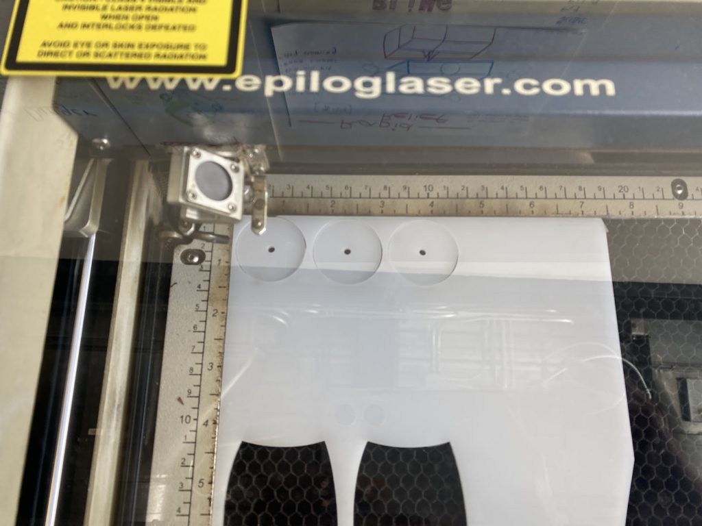
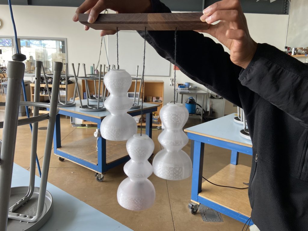
Fabrication
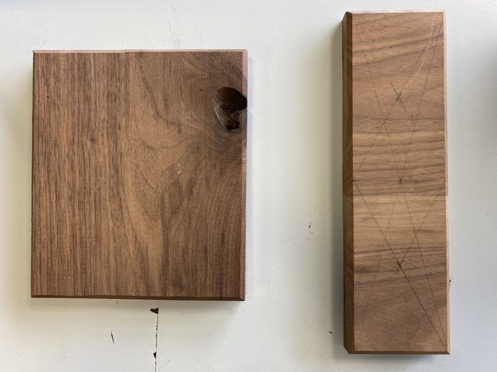
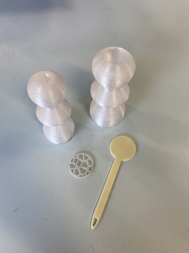
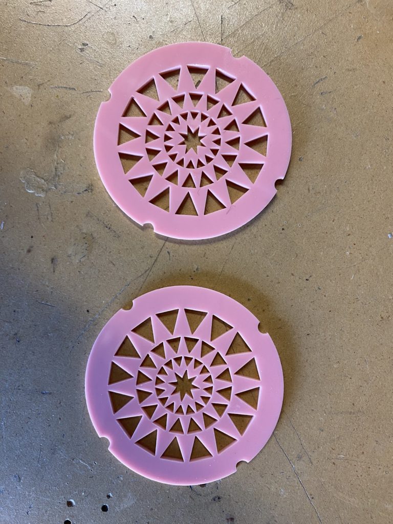
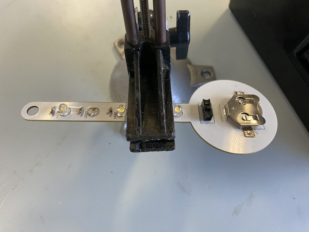
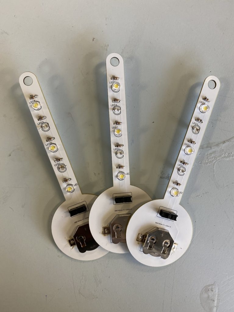
Early progress photos – working on the PCB, 3D printing shape, wood base, and acrylic base
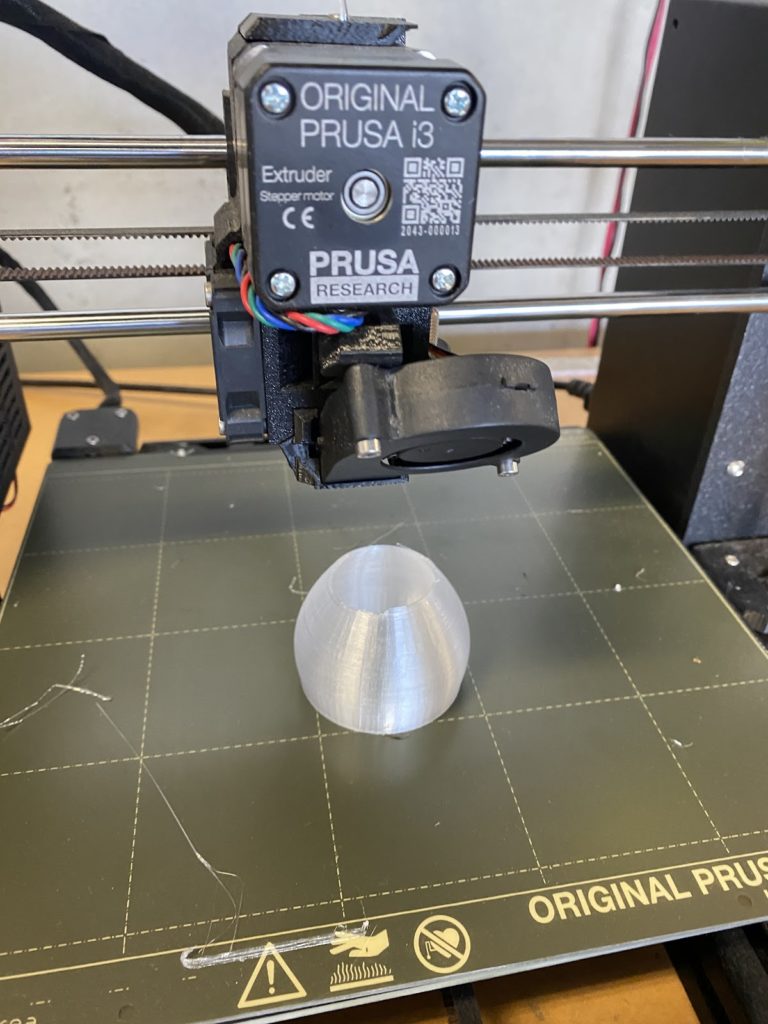
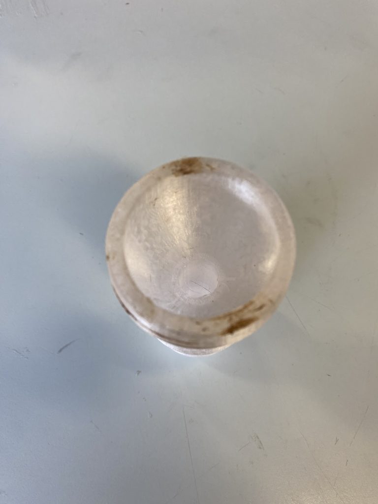
resulting in the brown spots above
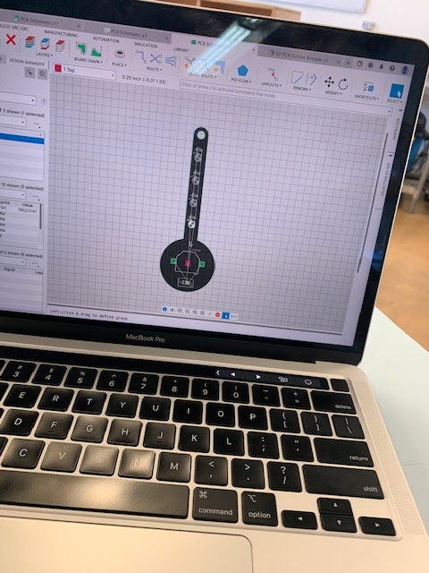
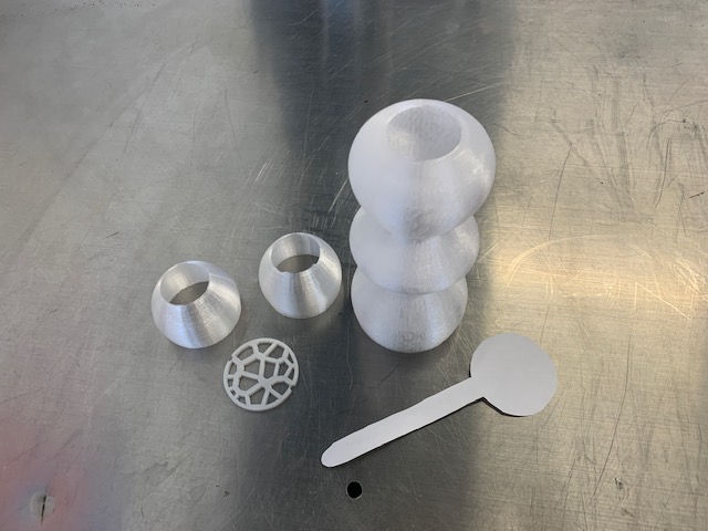
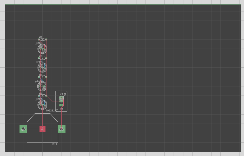
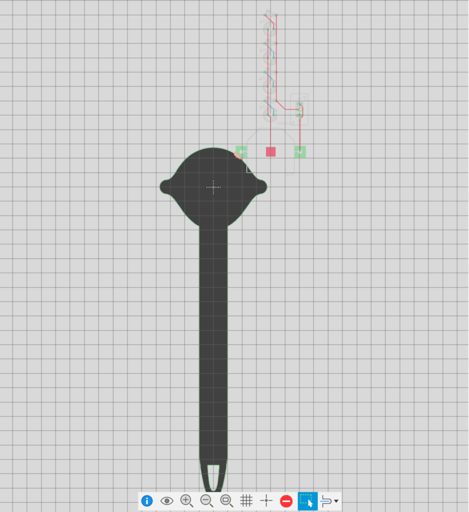
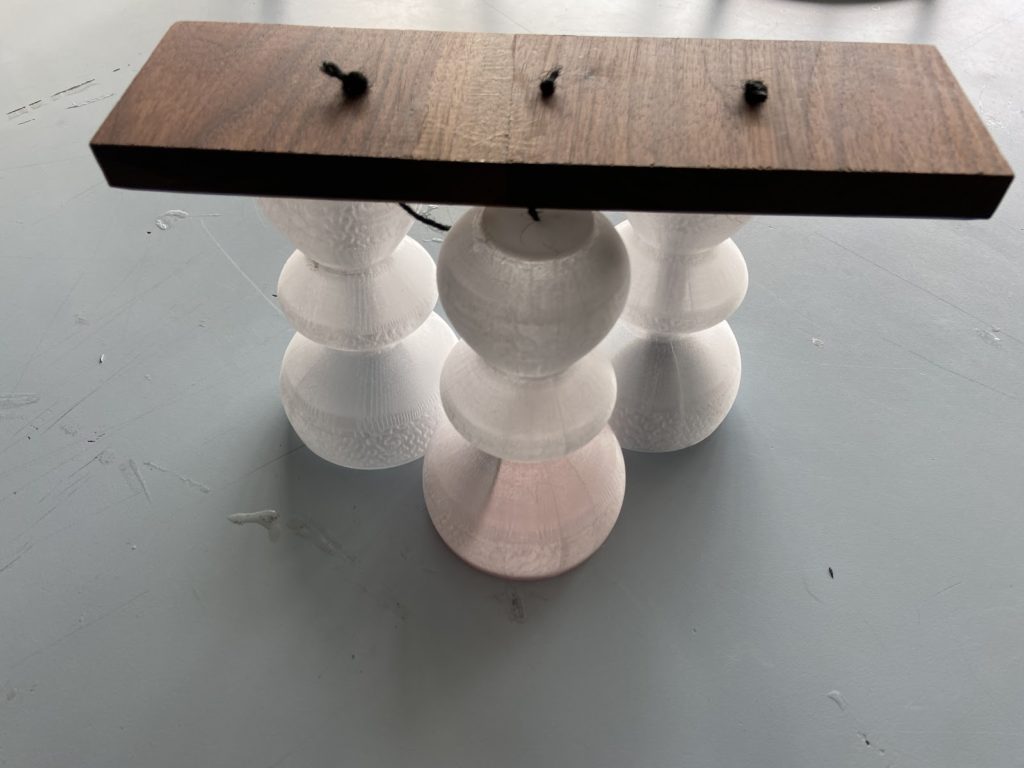
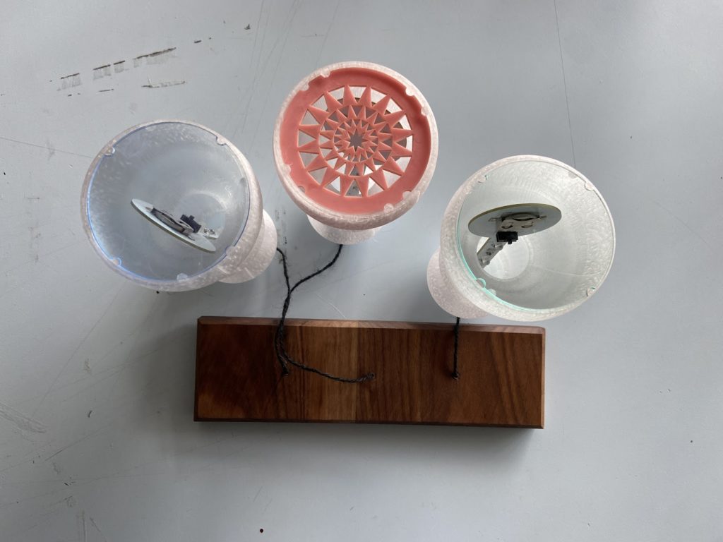
At this point in our design process, we thought we would screw the PCB in place into the lamp using the two stubs on the sides of the outline. But realizing we could just make the circular part of the PCB bigger than the holes in the lamp, it could hang on itself. We then simplified our design.
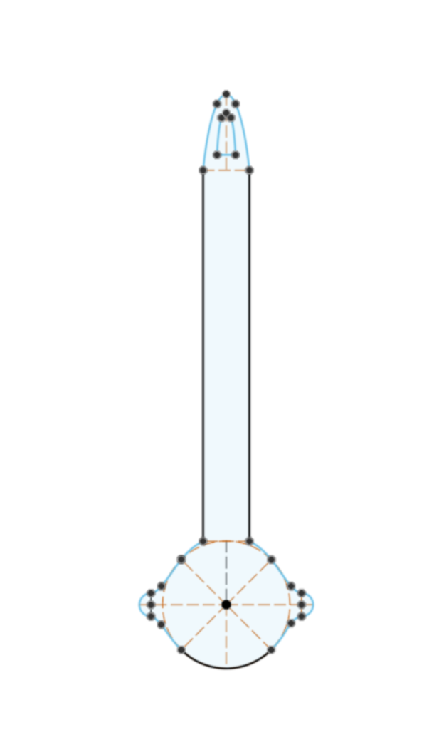
outline (ready to be ordered)
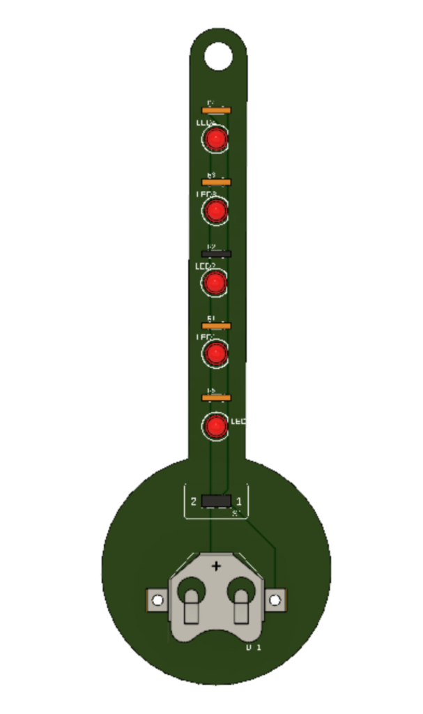
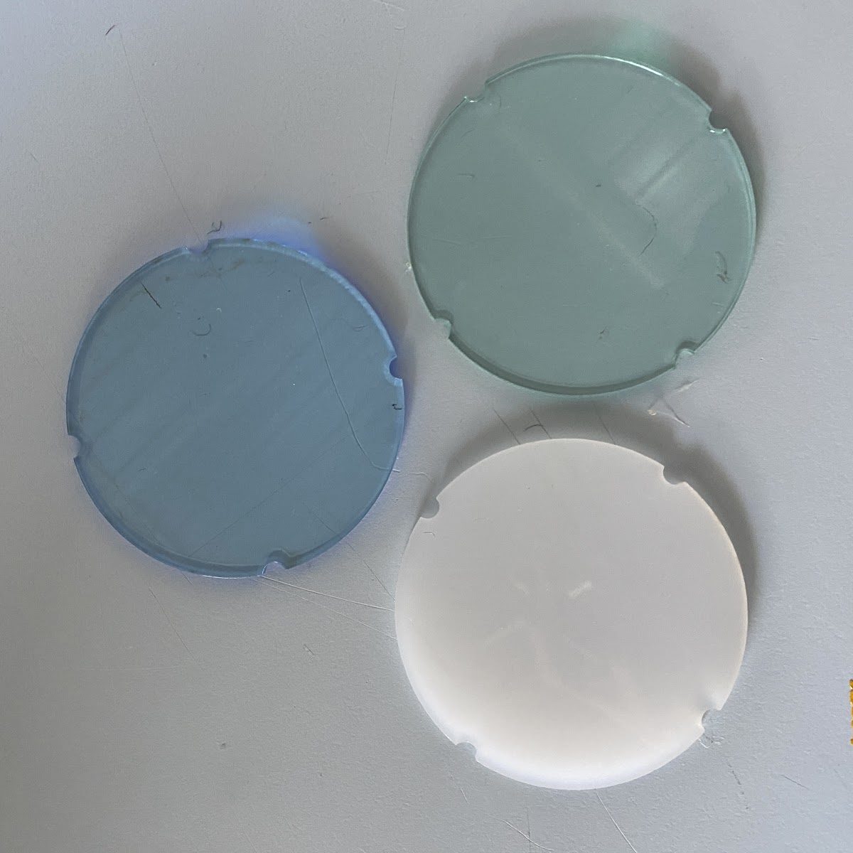
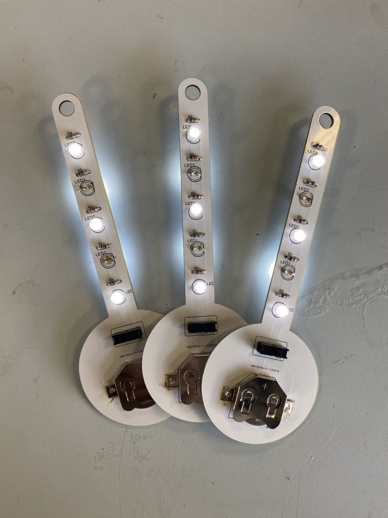
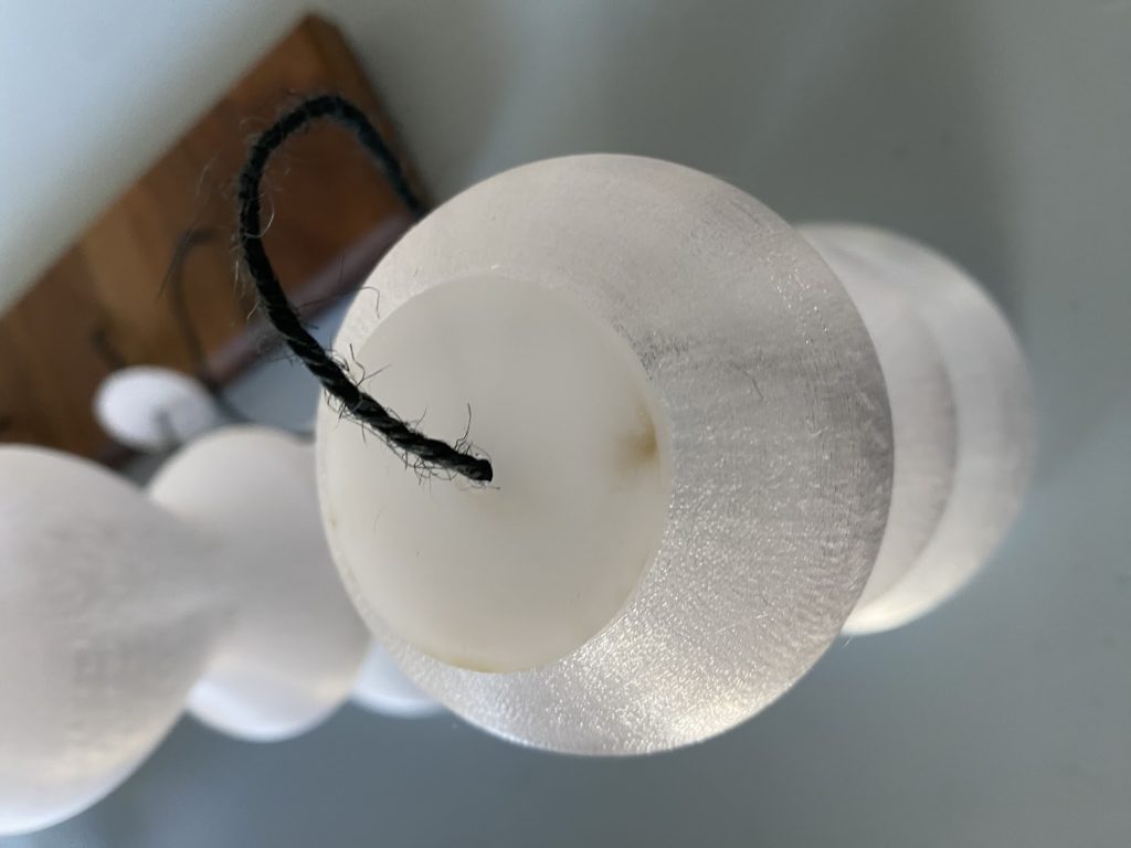
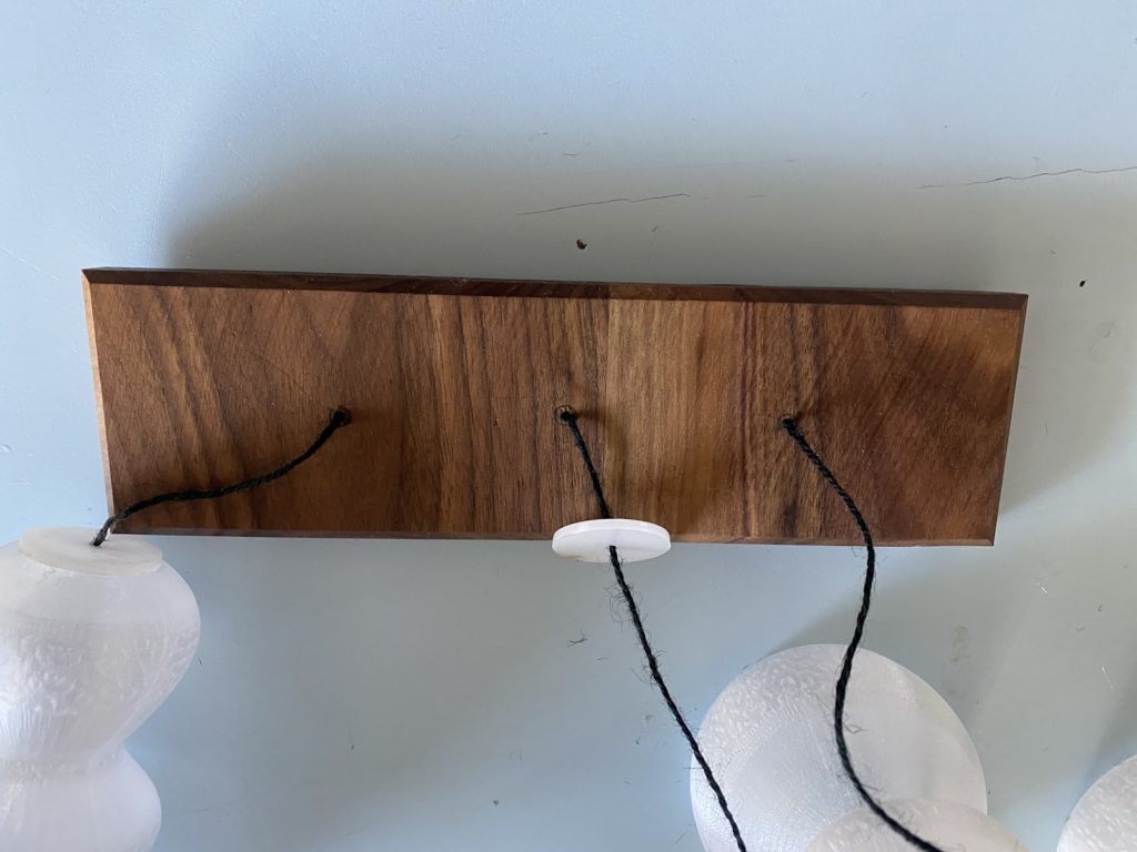
Final Product:
Makerspace Cart
This makerspace cart was designed as part of a community service initiative to supply schools in need with better opportunities to develop STEM education at their institutions. We worked with Mission Science of San Francisco and YEF to get this project funded and connected to a receiving school in the Bay Area.
Reviewing Previous Design + Feedback
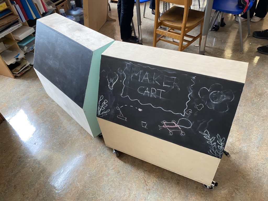
This is the original iteration of the makerspace cart in action:
Design
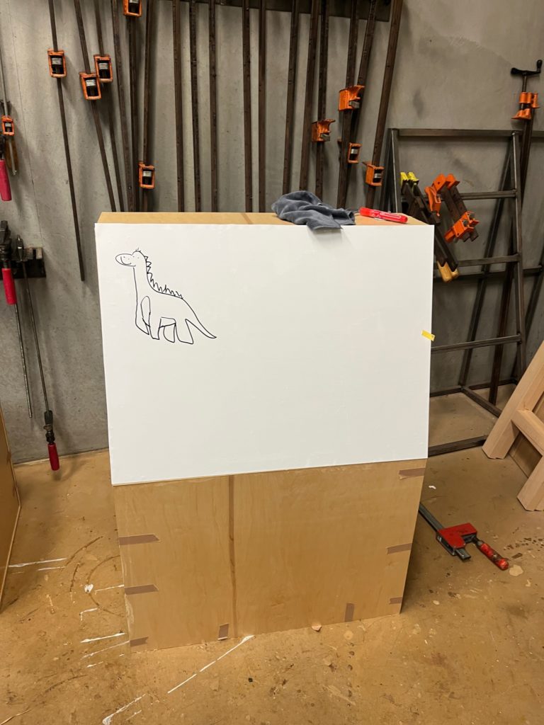
It worked well, but there were some things that could have been better, such as more compartments, easier mobility, and a more kid-friendly design.
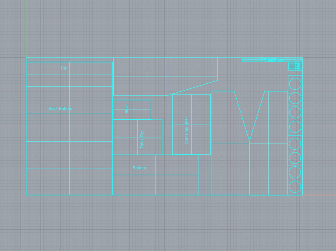
We started with redesigning the cart in Rhino, our 3D modeling software. These are some version of creating a 2D layout to fabricate:
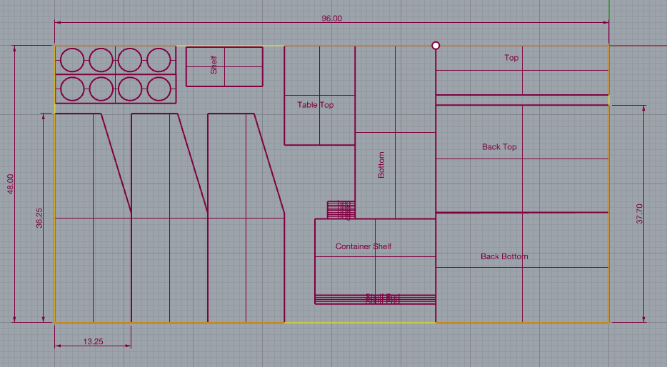
We decided to make the cart taller, less wide, have more container holders, and to use mitered edges instead of butt joints to make our cart less rough around the edges.
We also made multiple small prototype versions of possible designs to test what looked best:
After more edits, this is what our final design looked like:


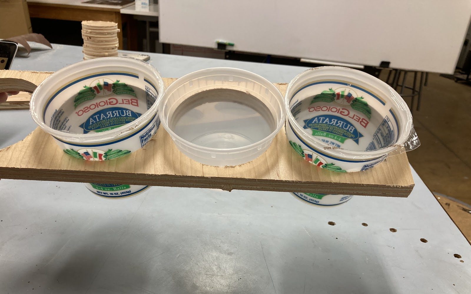
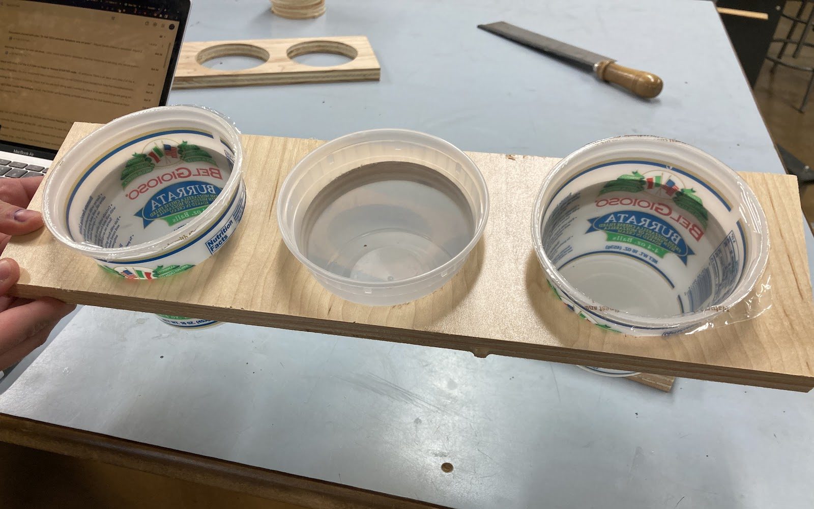
We also did some redesigning and testing for our container holders:
Fabrication
Cutting Stage
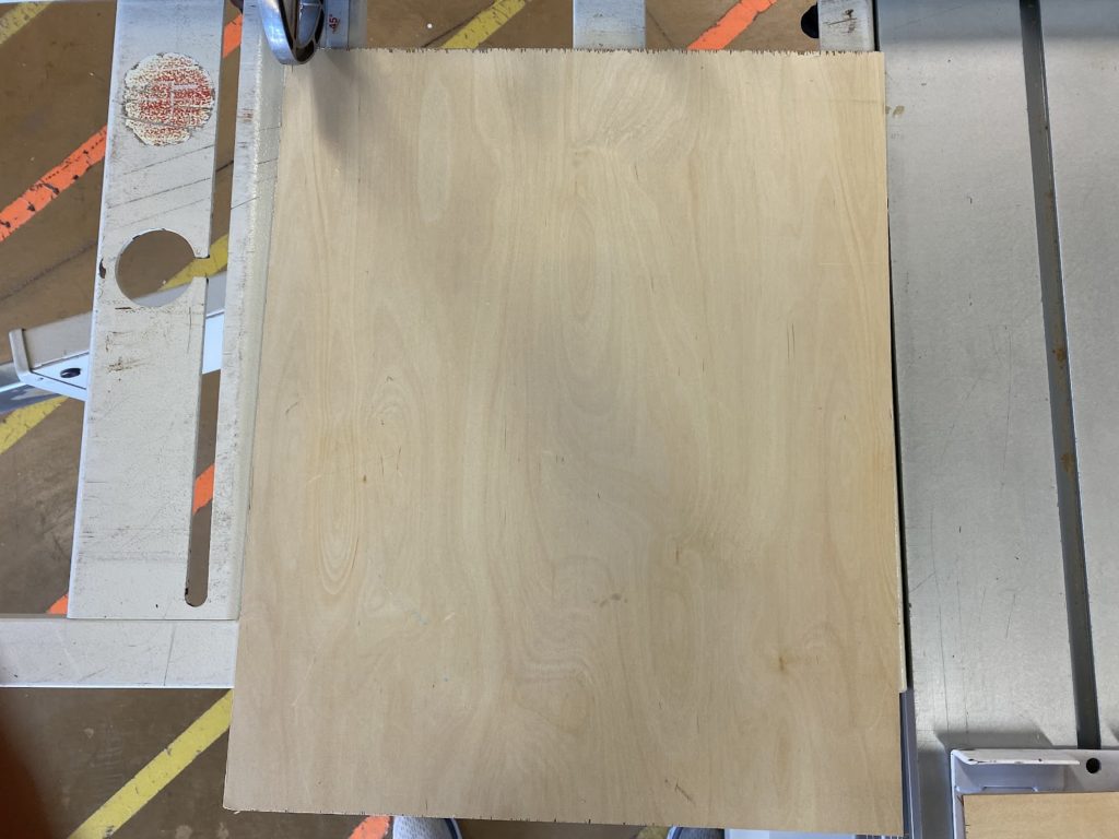
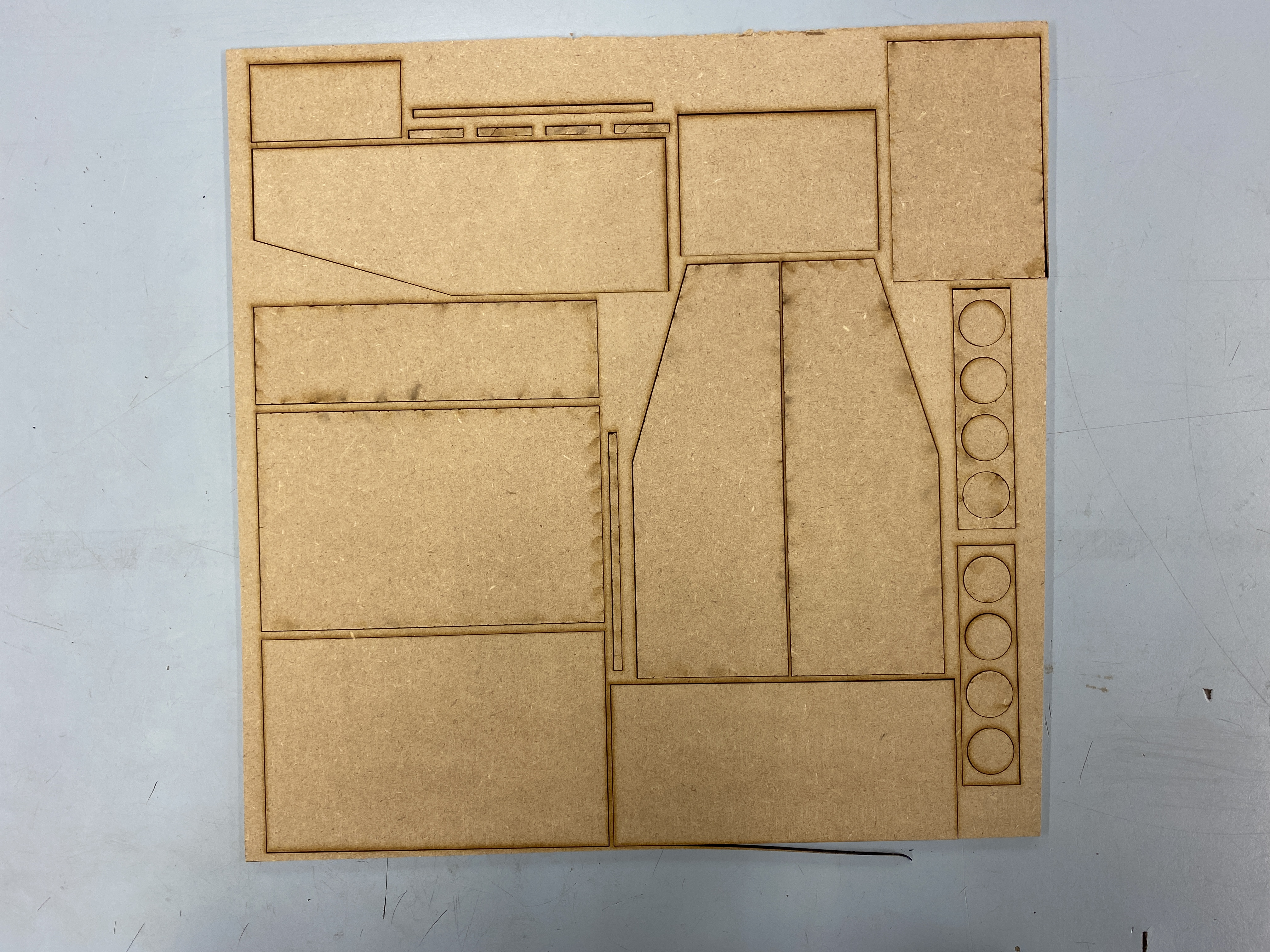
We started with large sheets of plywood and used the table saw to cut them in ways where we could reuse portions of the wood for many different parts of the cart:
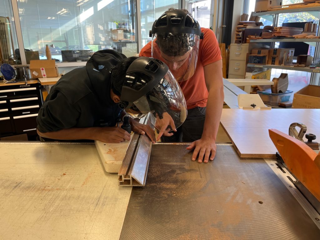
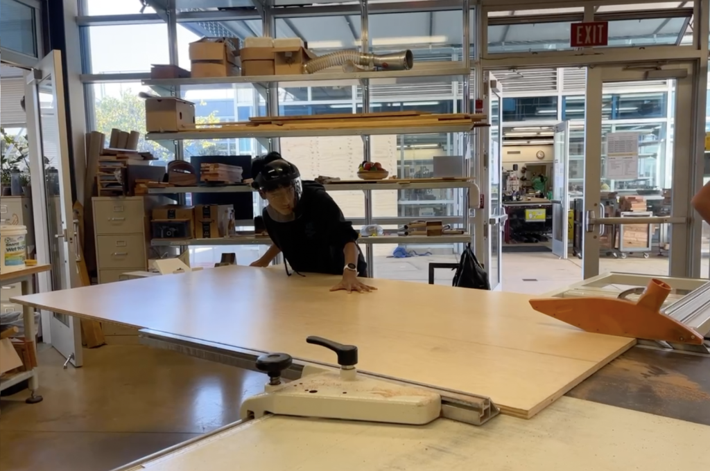
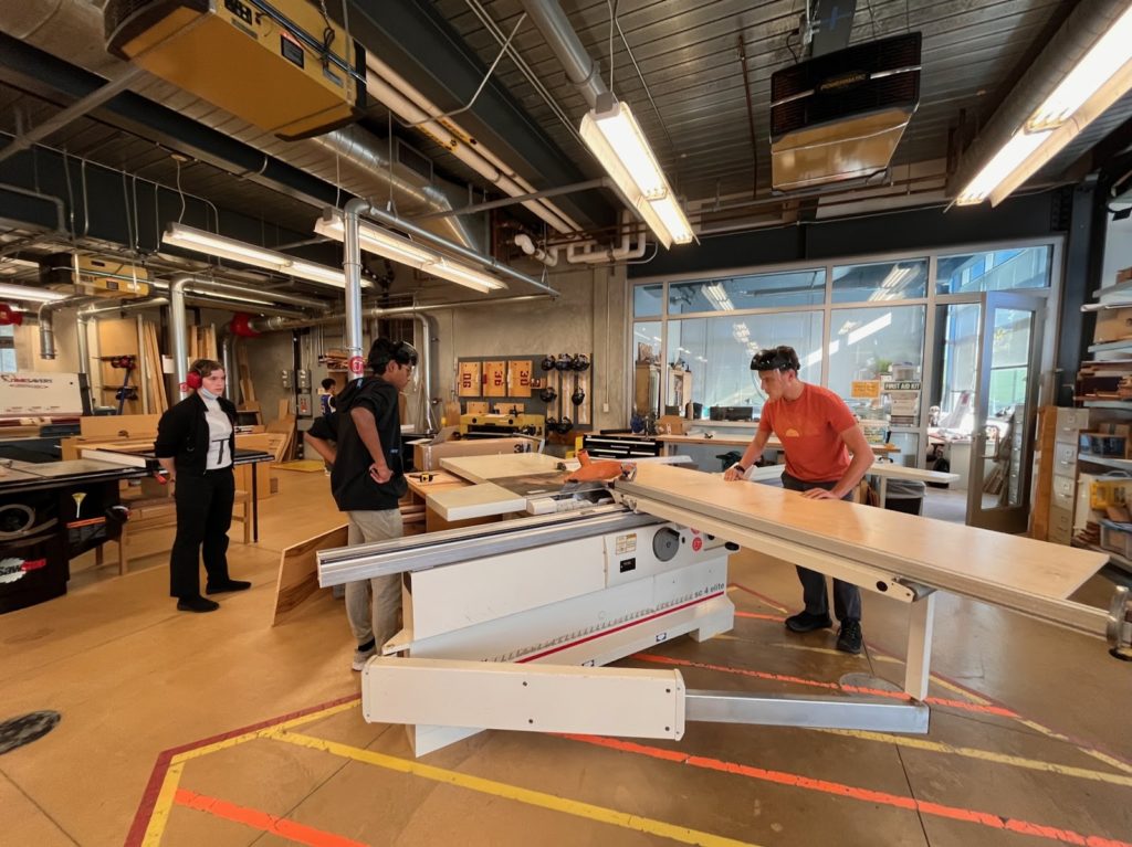
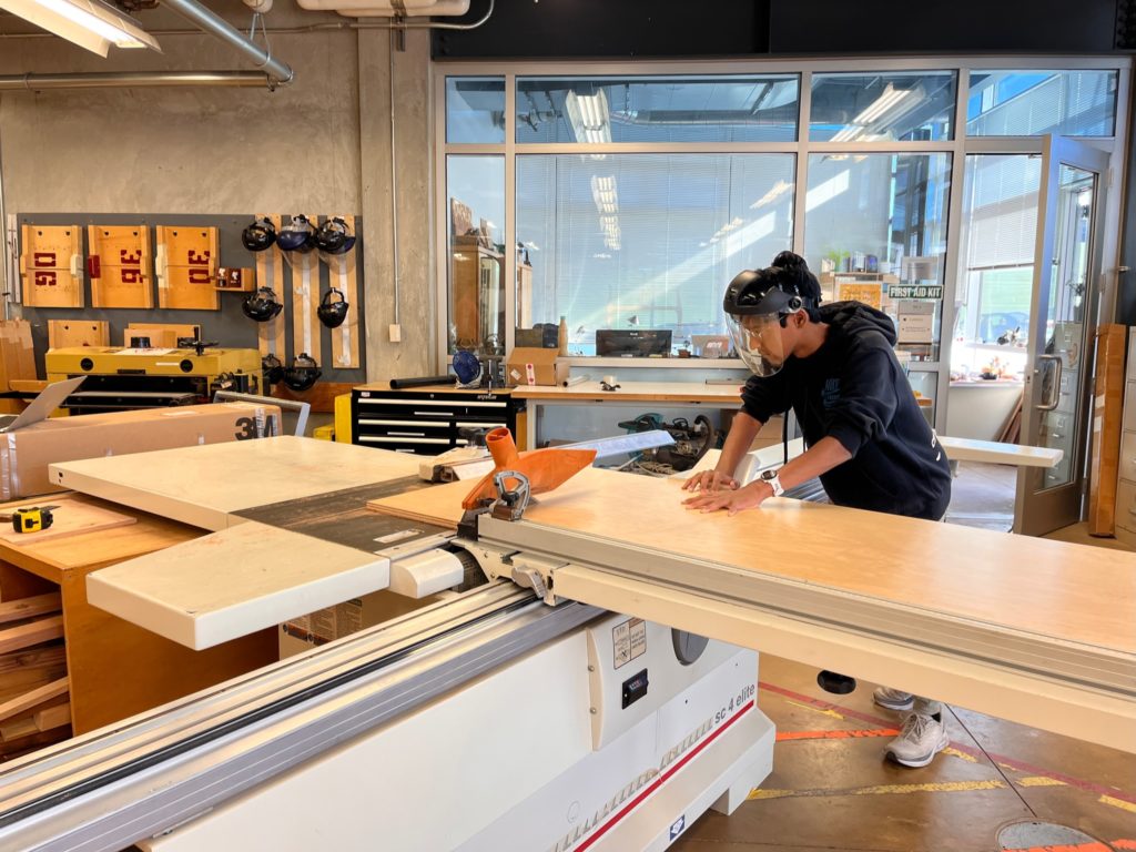
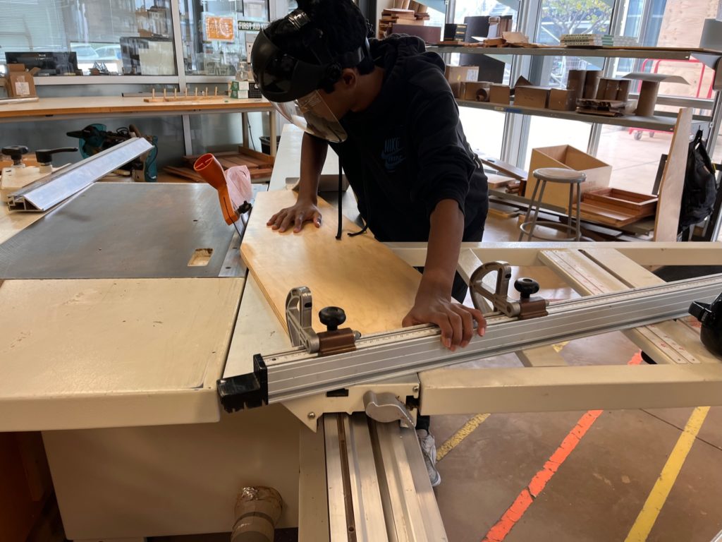
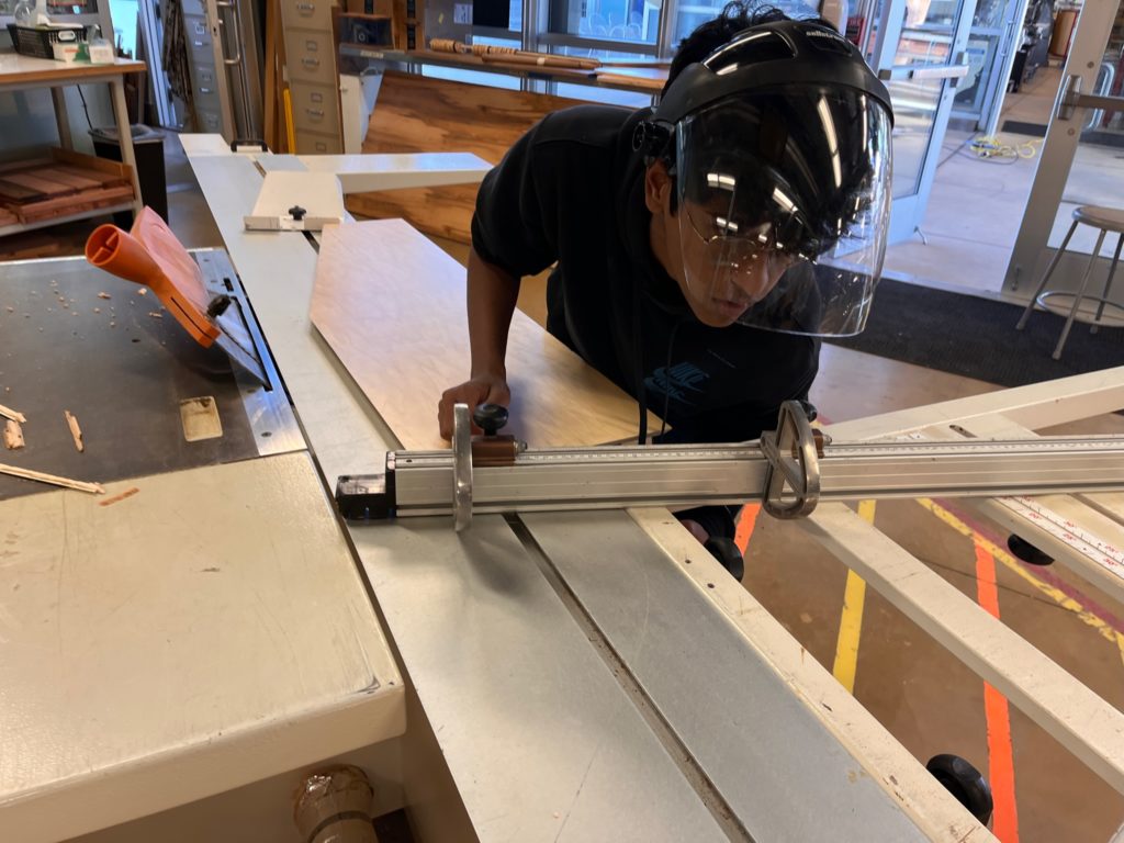
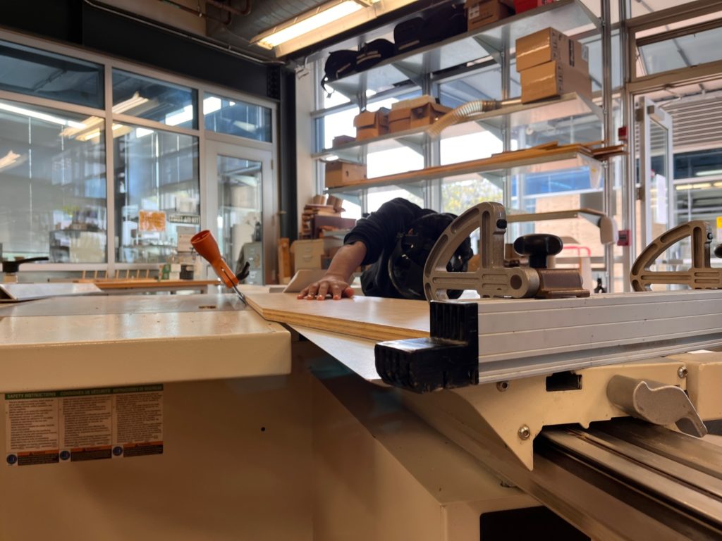
As can be seen above, we had to a lot angling and precise cuts on the table saw to get the proper slants and mitered edges for the back of our cart. This process was extremely difficult, as we had to recut massive pieces multiple times, re-angle many times, and did a lot of trial and error.
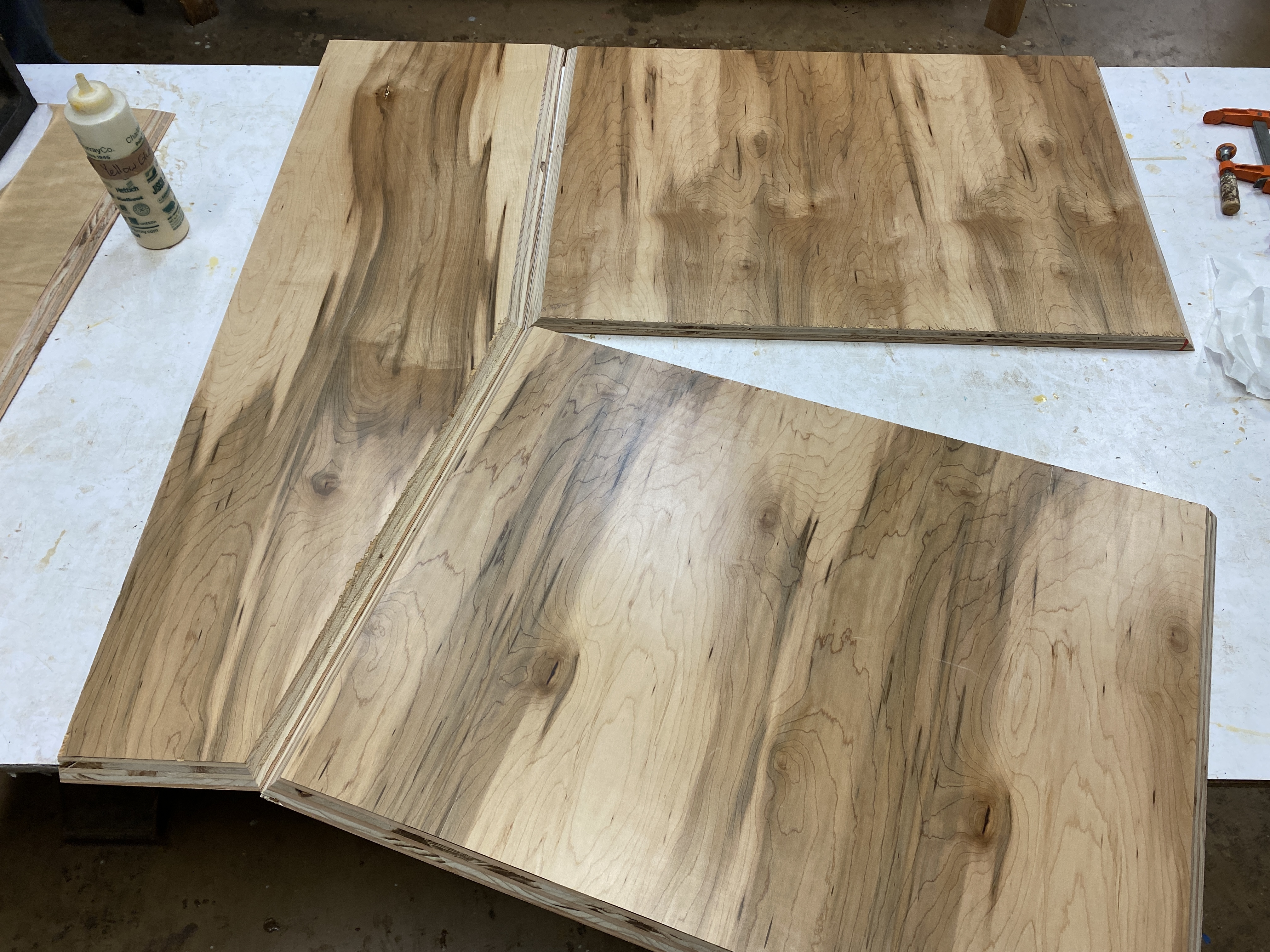
These are some finished pieces and how they fit together:
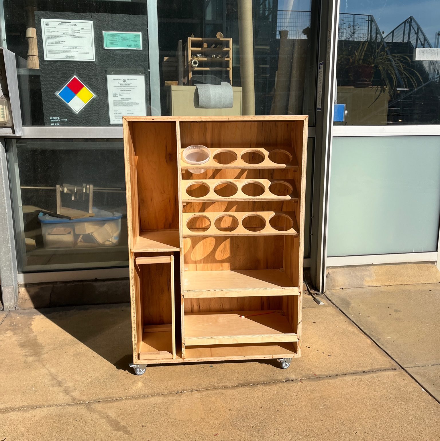
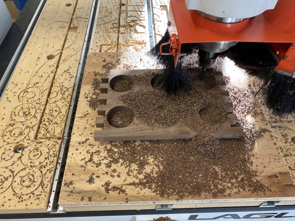
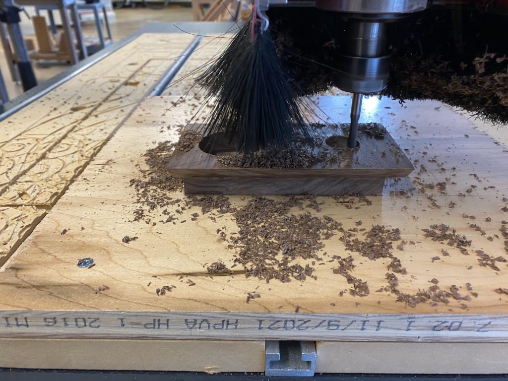
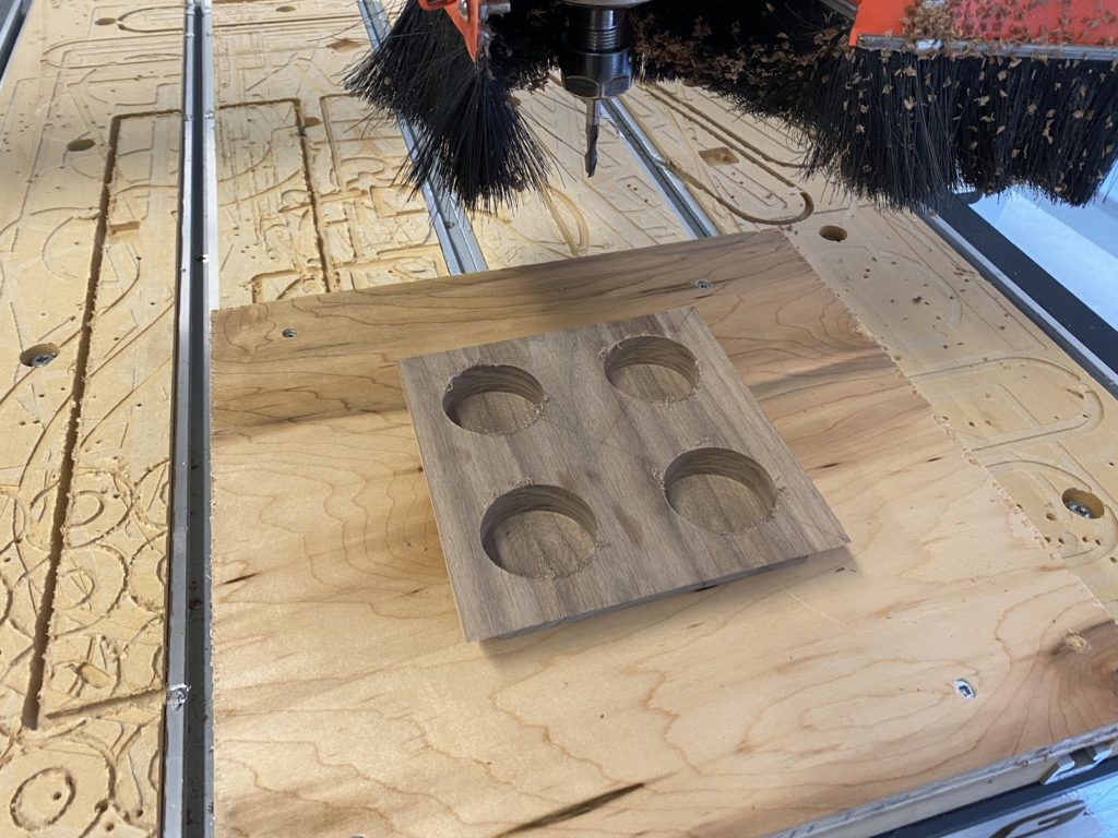
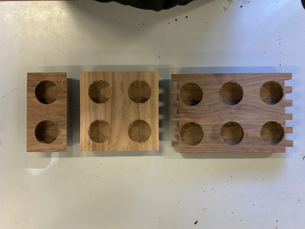
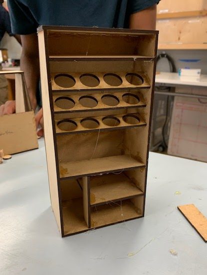
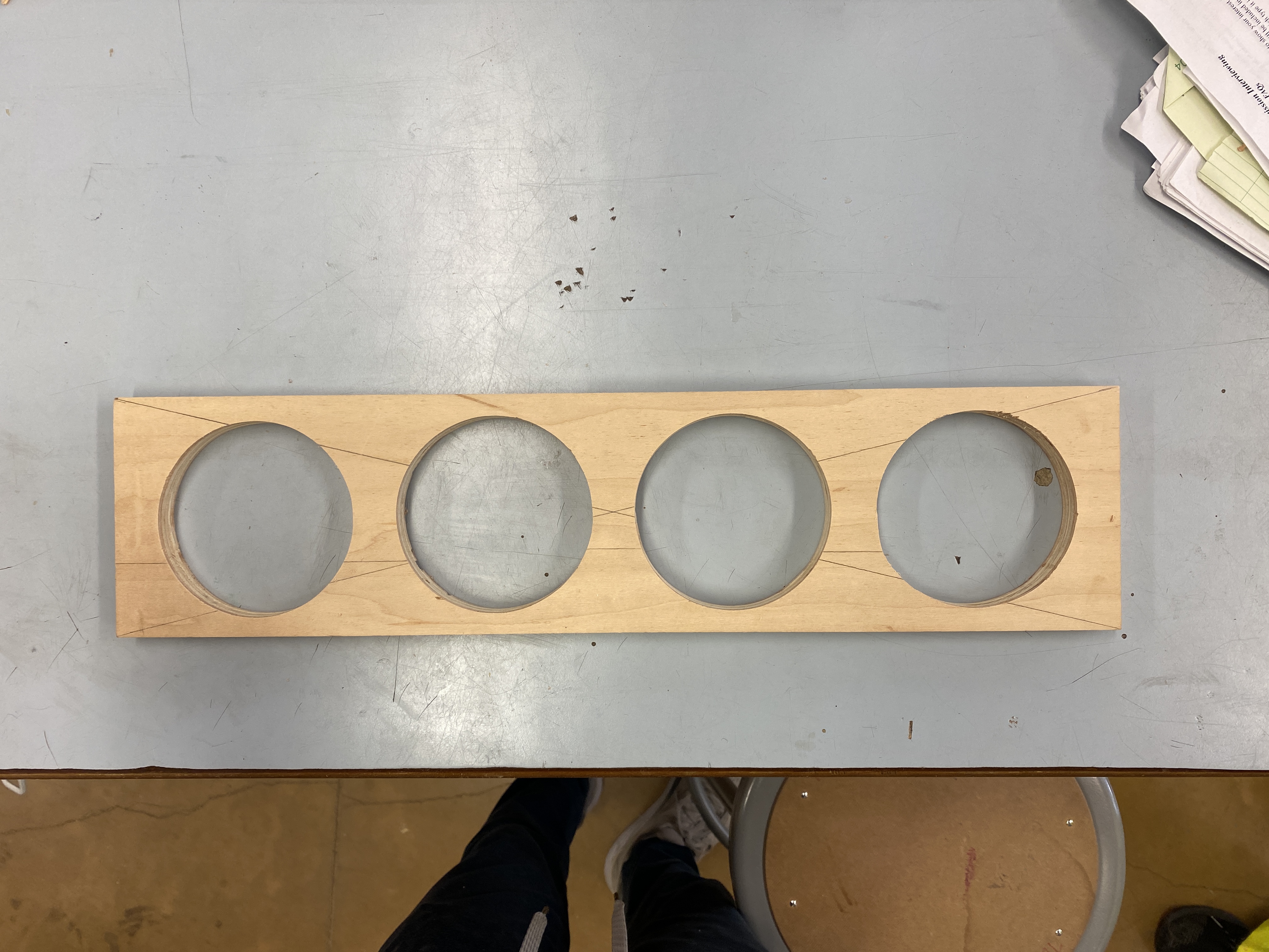
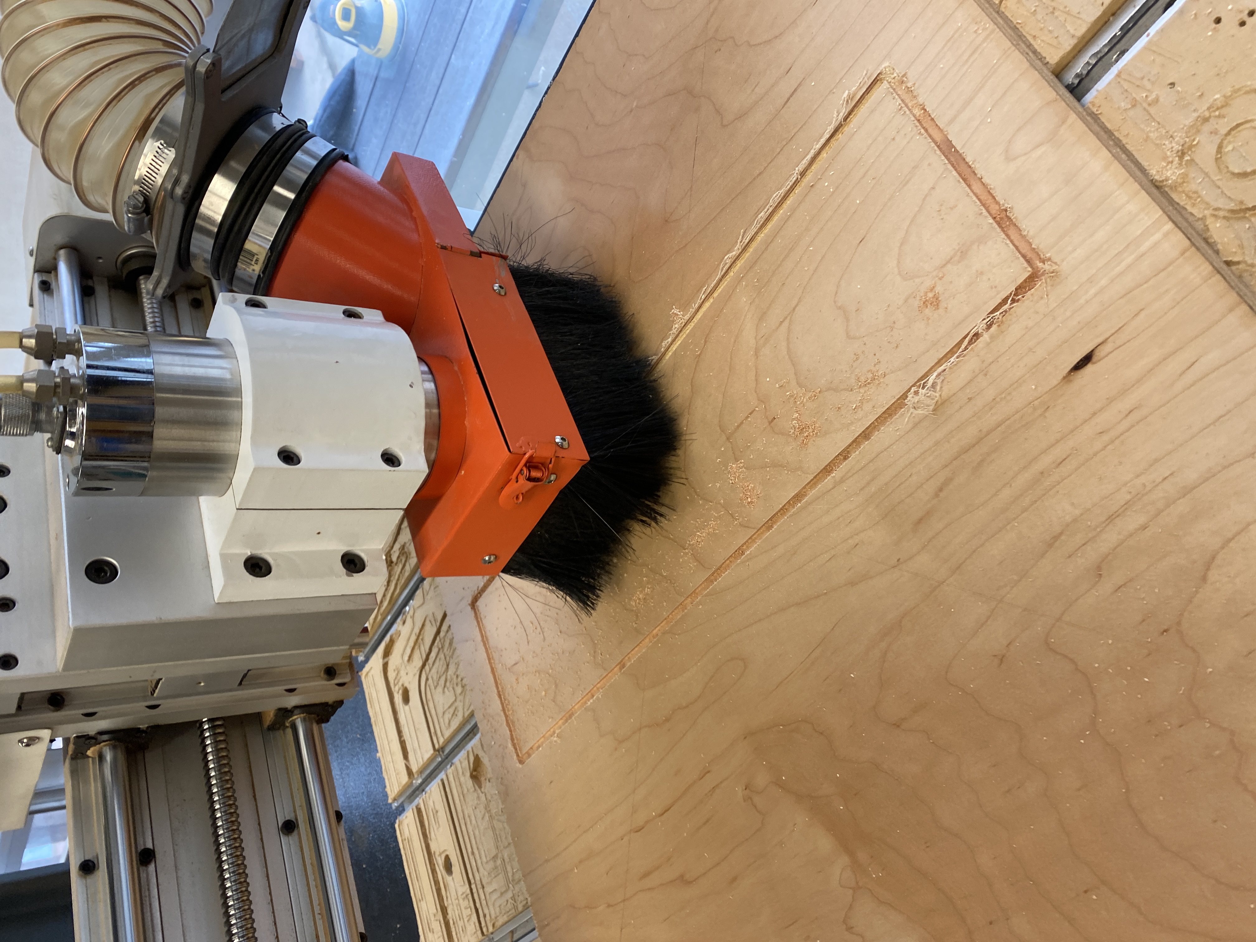
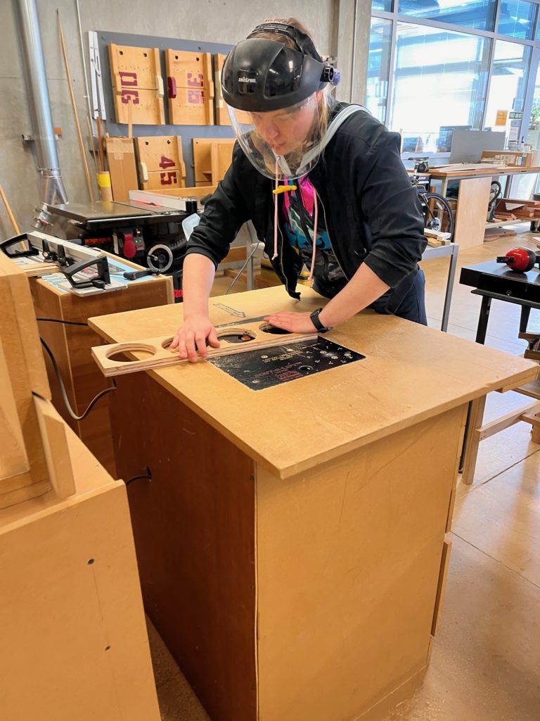
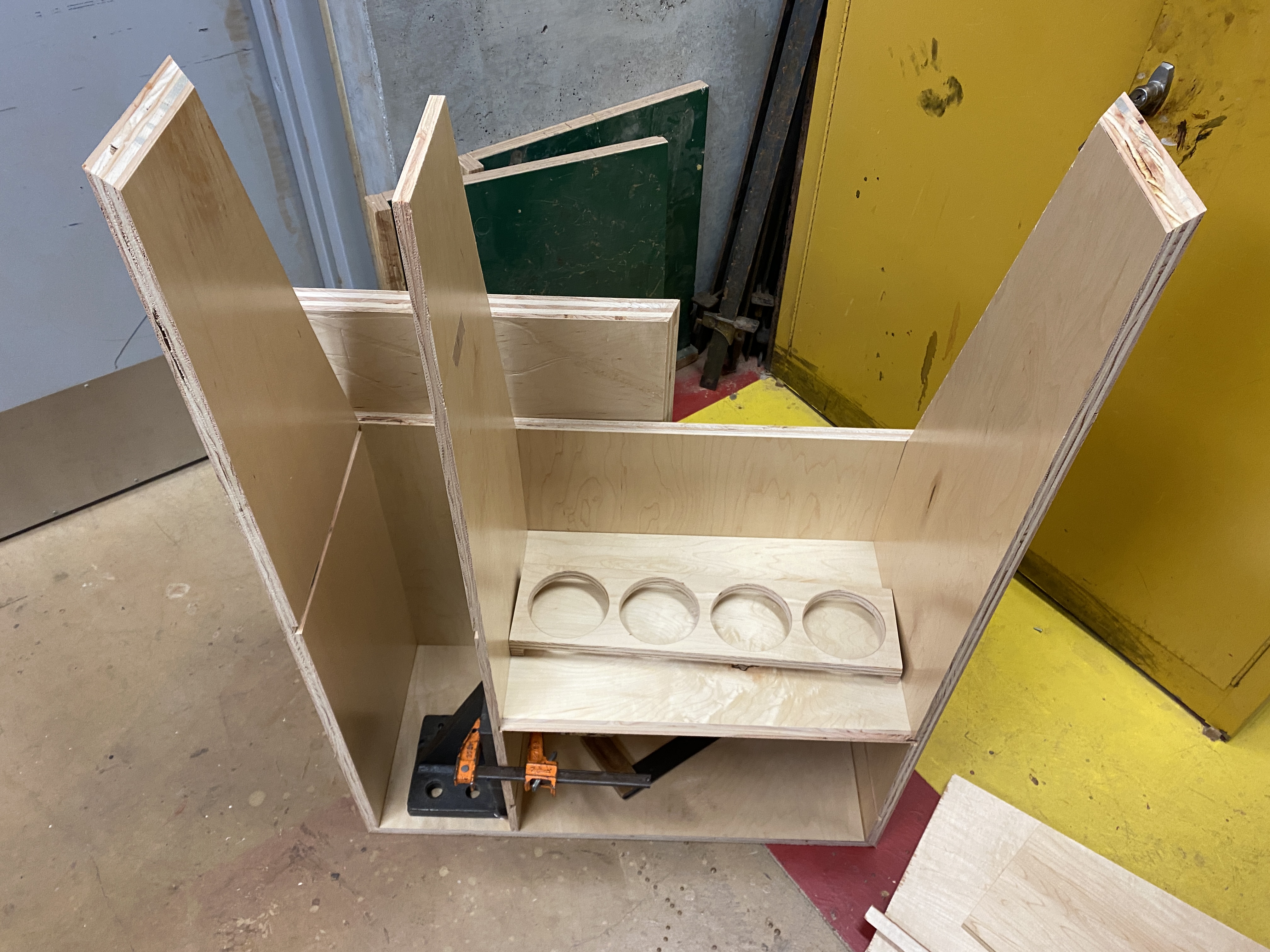
On the side while working on getting all our frame pieces cut, I was working on the CNC router to get our container holders cut. We decided on the design with four holes to fit more containers, since our design was wide enough to fit them:
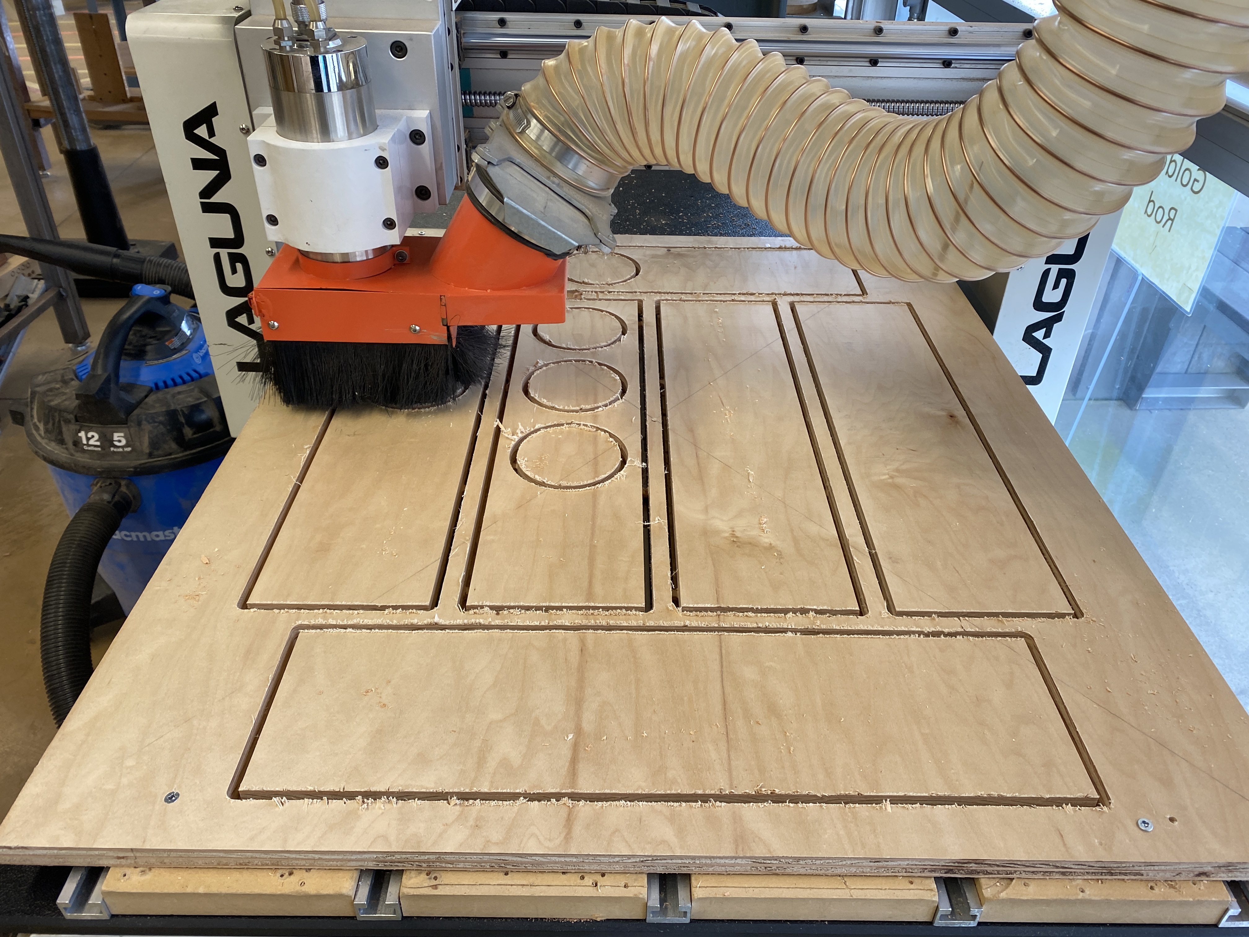
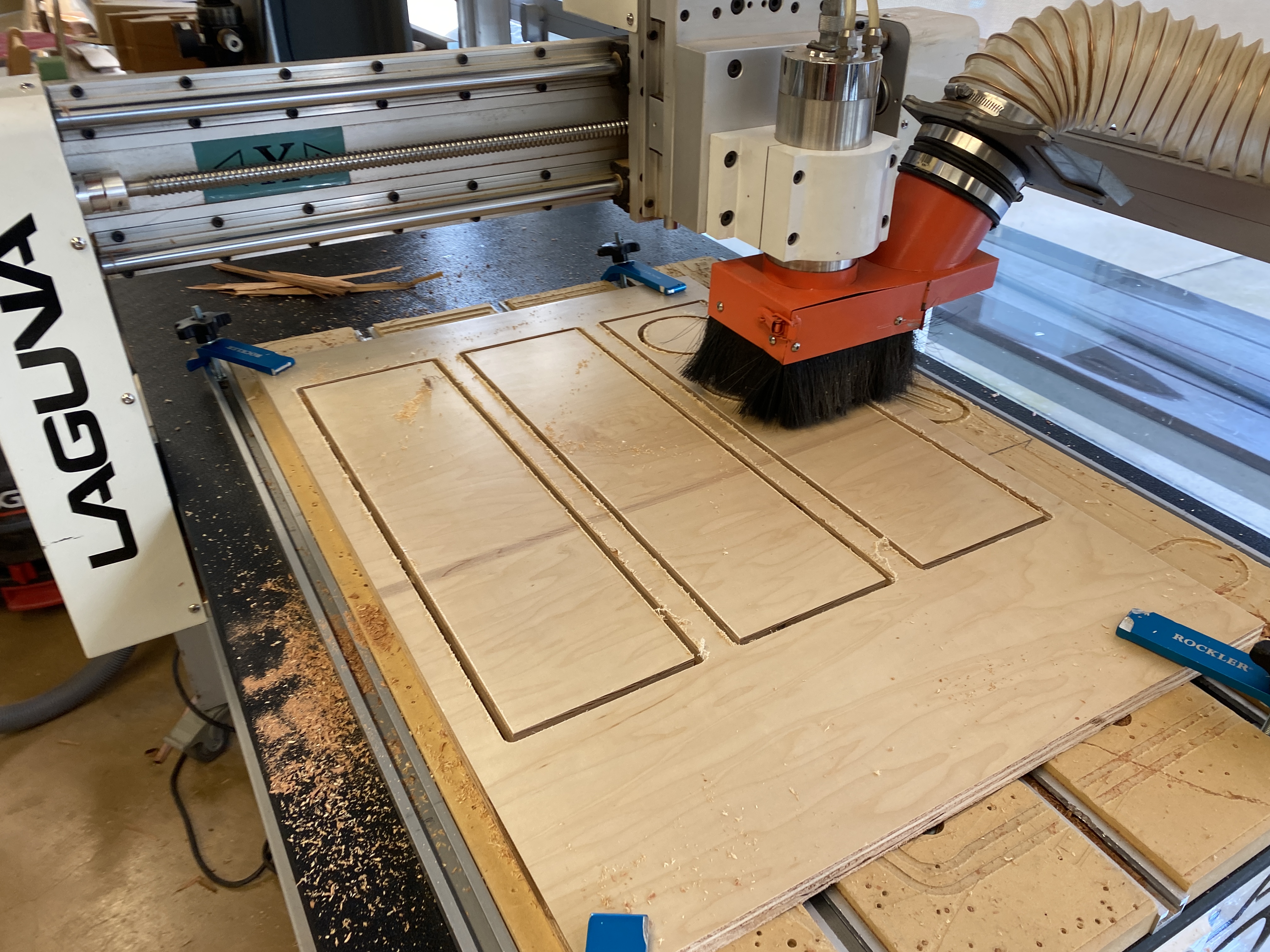
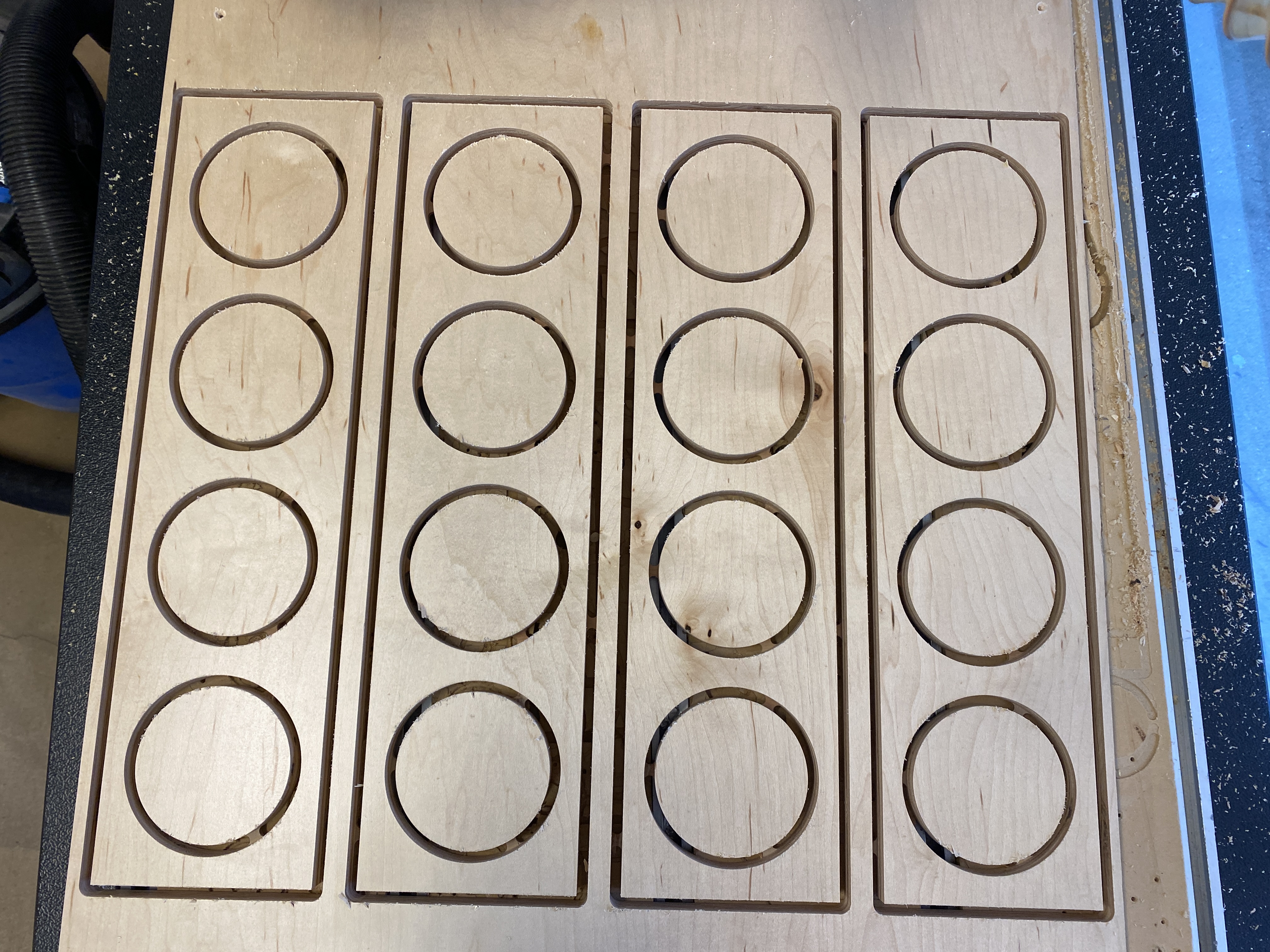
This process was also very difficult, as I had to find a way to cut many pieces at once without the wood moving, within the range of the machine’s movement and the router properly leveled. My routing bits broke multiple times, and I had to repeat the process of aggregating and exporting files from Rhino, manipulating DXFs and creating cutting paths in Aspire, and actually cutting on the machine. But the result was great, and all the pieces we ended using came out clean and accurately cut with the exception of some pieces of plywood layer chipping off.
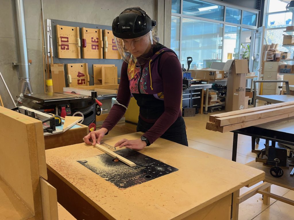
We also routed the corners of the holders and the ledges on the shelves so they wouldn’t be sharp to the touch:
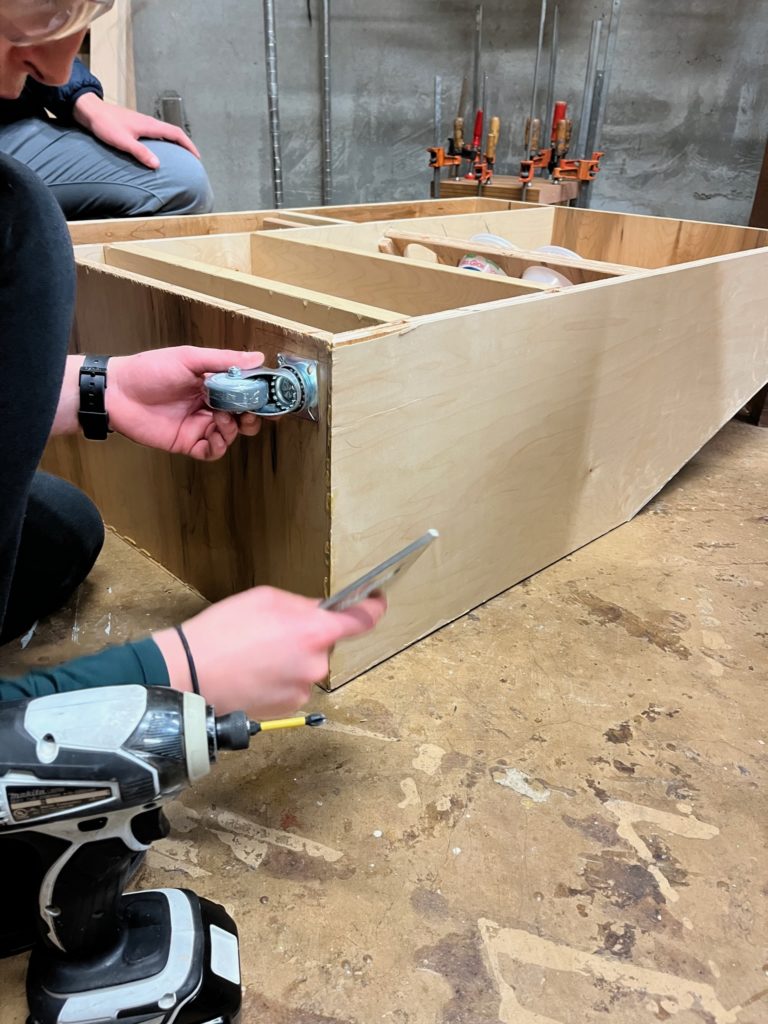
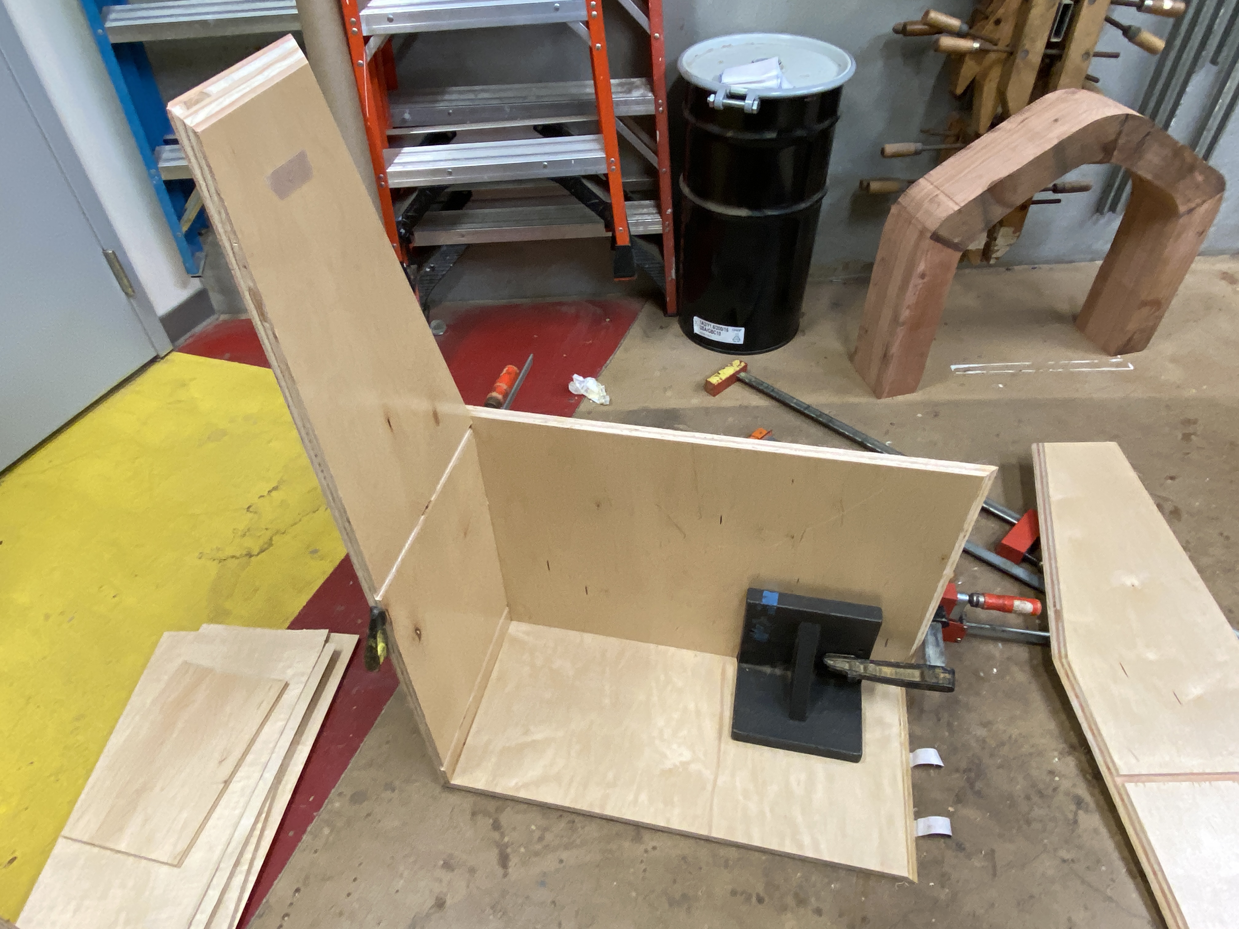
Assembly Stage
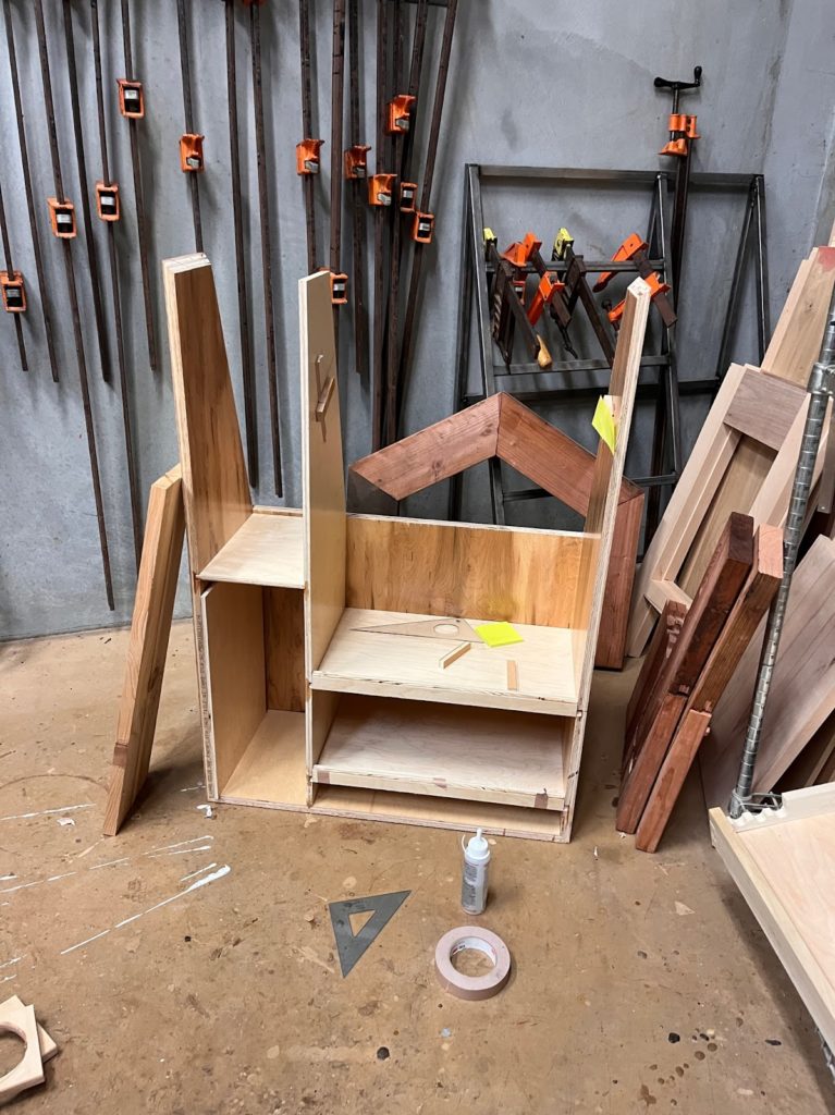
After all our pieces were cut, we started to put everything together. Below is a picture of our first dry prototype:
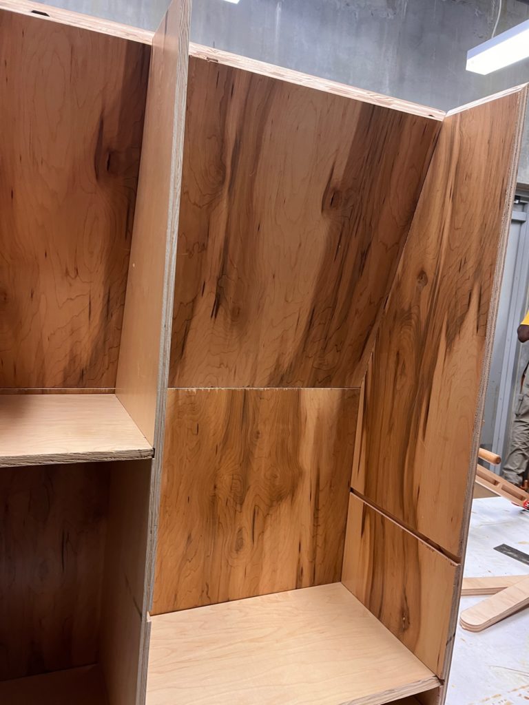
We added many grooves into our walls to make adding shelves less messy, and they ended up being very good fits for our shelf pieces. All our slanted and mitered frame pieces fit together for the most part, with some small gaps due to inevitable cutting inconsistencies with our more complicated cuts on the large table saw.
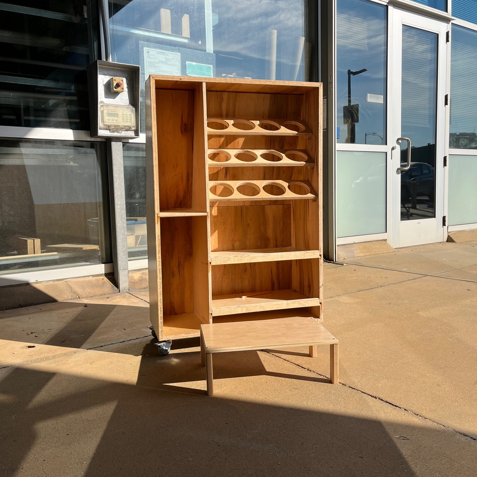
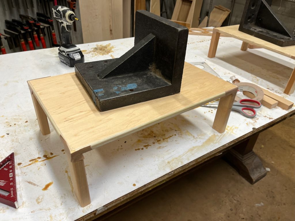
We also cut, mitered, sanded and glued our mini-table for the drill press that would sit in the compartment on the bottom left in the above photo:
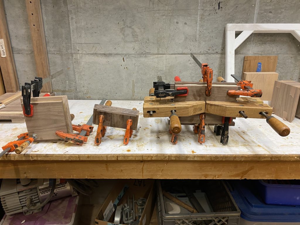
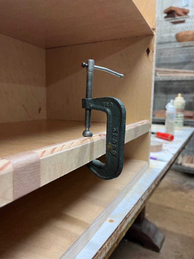
We started to glue and clamp pieces together:
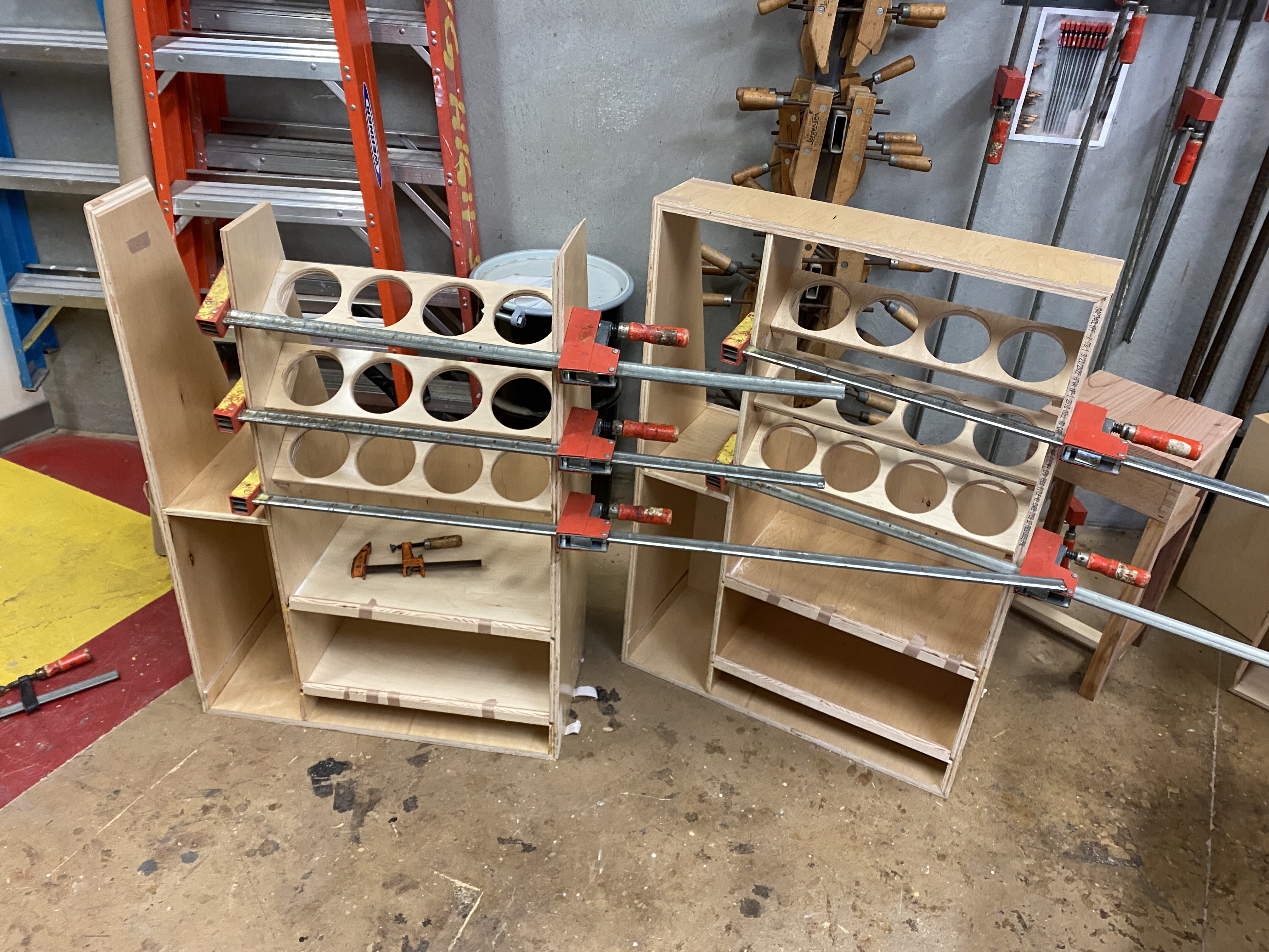
After gluing, we did some final touches, such as filling gaps with wood filler, glue and sawdust, and sanding and cleaning up the edges to make the sides less sharp.
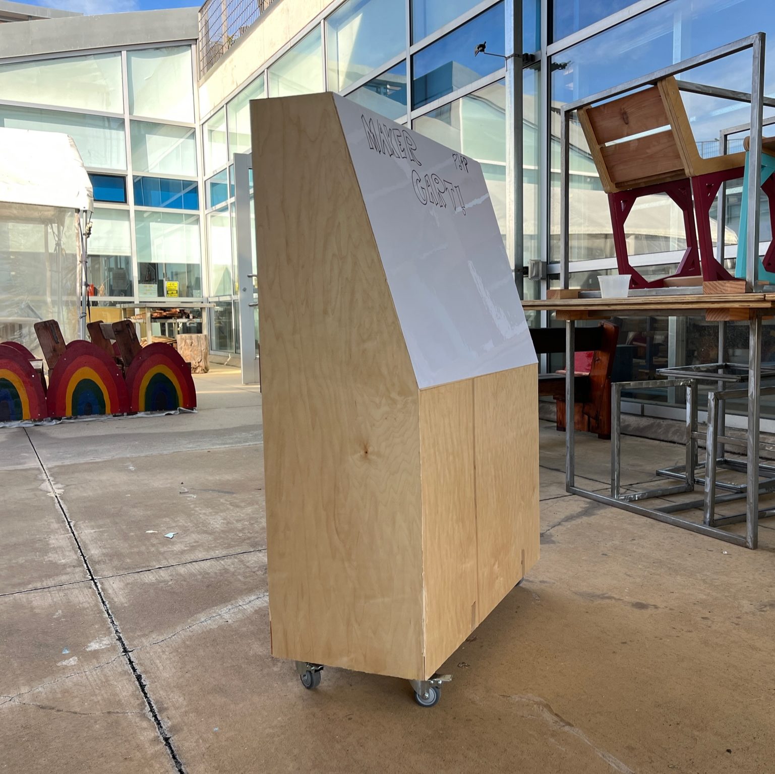
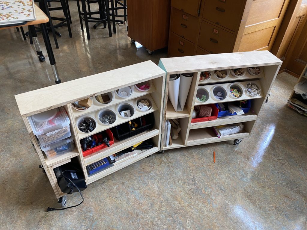
We made two of these carts to be sent to the school we made these for (we worked with the staff from Mission Science to get these transported). These are the final photos of our carts: