Phone-Controlled Robot Arm
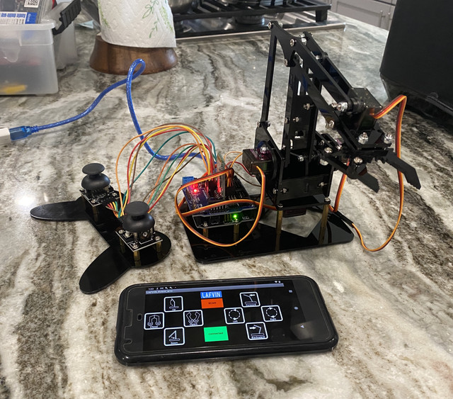
This project was chosen as part of the BlueStamp Engineering program, where I built and coded a wireless robotic arm under a mentor using an Arduino, numerous servo motor, laser cut acrylic pieces, and MIT App Inventor. To the left is a picture of the finished product.
First Milestone
My first milestone was setting up and hooking up the Arduino Uno with a servo and a Bluetooth reciever. I first started with connecting my Arduino board with another board called the Arduino Sensor Shield v5, the sensor shield on top of the arduino. This will allow me to connect multiple servos at once very easily. I connected one servo to the sensor shield board and connected my Arduino to my computer to make sure my servo worked properly. I wrote a simple program to rotate a servo back and forth to test its range of motion and to experiment with coding servos. I ran into a couple of issues along the way. The first was from getting the error “Compilationerror: error 13 INTERNAL”, which came from not having the servo library installed. My other issue was with the sensor shield board, as when I connected a servo to the proper pins on the board, sometimes the servo would be unresponsive. I easily fixed this by using a different servo.
Second Milestone
My second milestone was fully assembling my robot arm and operating it via potentiometers. I started with separating all my screws into their various lengths and went step by step assembling my robot. I then mounted my Arduino onto the bottom plate of my robot, and connected my 4 servos and HC-05 bluetooth sensor to the sensor shield v5 board on top. After testing the ranges of motion for each of the servos in my robot arm, I wired four potentiometers to my sensor shield board’s analog, ground and VCC pins, and wrote a program that would read the values of the potentiometers and convert those readings into positions for my servos. Some challenges I ran into were with assembly, as there were many different lengths of screws and types of nuts, and I had mixed some of the placements of certain screws up. Because of this, I had to redo parts of my assembly, which took more time. Lock nuts were also very hard to fully screw in, and took lots of effortand time as well.
Final Milestone
My final milestone is my robot arm complete with HC-05 bluetooth mobile control and PS2 joystick control. The main premise of my project was to be able to control the robot arm wirelessly from a mobile device, and in this milestone I achieved that. I started with Bluetooth control, and writing some code to allow for bluetooth connection my Arduino. Once done, I developed an app on MIT App Inventor for wireless robot control and to commmunicate with the Arduino via Bluetooth. After I got my bluetooth app working with the robot, I transitioned to making a modification, using the PS2 joystick sensors. I wired each of the pins to the corresponding analog, ground and VCC pins and wrote a sketch file for control with the joysticks, which was similar to my potentiometer code but with many more variables and analog inputs. Through both the bluetooth and PS2 control parts of my project, I encountered a lot of problems. Namely the bluetooth module code had to be tweaked countless times to establish a bluetooth connection. Also, at first, I didn’t have access to an Android device, which was important because using bluetootth with MIT APP Inventor only works on Android (iOS has some privacy and secuirty featuers that don’t allow such direct bluetooth connections). With the PS2 joysticks, when using the library built for PS2 controller use on Arduino (PS2X_lib), the controller wasn’t being detected, even though my wiring was correct, so I had to alter my code quite a bit to work without the module.
Final Code Snippets
Code for bluetooth control with the HC-05 bluetooth module and an Android device:
#include <Servo.h>

Servo myservo1;  // create servo object to control a servo
Servo myservo2;
Servo myservo3;
Servo myservo4;
int pos1=90, pos2=90, pos3=90, pos4=90;  // define variable of servo angles + assign initial angle
char val;
int incomingByte = 0;          // Received data byte
String inputString = "";         // Used to store received content
boolean newLineReceived = false; //  Previous data end flag
boolean startBit  = false;  //Acceptance Agreement Start Sign
int num_reveice=0;


void setup()
{
  myservo1.attach(3);    // set the control pin of servo 1 to 3 digital I/0
  myservo2.attach(5);    // set the control pin of servo 1 to 3 digital I/0
  myservo3.attach(6);    // set the control pin of servo 1 to 3 digital I/0
  myservo4.attach(9);    // set the control pin of servo 1 to 3 digital I/0

  myservo1.write(pos1);
  myservo2.write(pos2);
  myservo3.write(pos3);
  myservo4.write(pos4);
  delay(1500);
  Serial.begin(9600); //  set the baud rate to 9600
}

void loop()
{
while (Serial.available())
  {
    incomingByte = Serial.read();  //One byte by byte, next sentence is read into a string array to form completed packet
    if (incomingByte == '%')
    {
      num_reveice = 0;
      startBit = true;
    }
    if (startBit == true)
    {
      num_reveice++;
      inputString += (char) incomingByte;
    }
    if (startBit == true && incomingByte == '#')
    {
      newLineReceived = true;
      startBit = false;
    }

    if(num_reveice >= 20)
    {
      num_reveice = 0;
      startBit = false;
      newLineReceived = false;
      inputString = "";
    }
  }

if(newLineReceived)
{
      Serial.println(inputString);
      if(inputString.substring(0,3)=="%4#"){
        Serial.println("Up");

         // raise the arm
        for(pos3;pos3<100;pos3++)
        {
          myservo3.write(pos3);
          delay(5);
        }
        delay(1500);

      }else if(inputString.substring(0,3)=="%5#"){
         Serial.println("Close");
        // close the claw
        for(pos4;pos4>45;pos4--)
        {
          myservo4.write(pos4);
        }
        delay(1000);


      }else if(inputString.substring(0,3)=="%7#"){


         Serial.println("Down");
         // Lower the arm
         for(pos3;pos3>40;pos3--)
         {
            myservo3.write(pos3);
            delay(5);
         }
         delay(1000);


      }else if(inputString.substring(0,3)=="%A#"){
         Serial.println("Forward");
          //  stretch out the arm
          for(pos2;pos2<130;pos2++)
          {
            myservo2.write(pos2);
            delay(5);
          }
          delay(1000);

      }else if(inputString.substring(0,3)=="%B#"){

         Serial.println("Left");
         for(pos1;pos1<150;pos1++)
          {
            myservo1.write(pos1);
            delay(5);
          }
          delay(1000);

      }else if(inputString.substring(0,3)=="%C#"){
         Serial.println("Right");
         for(pos1;pos1>30;pos1--)
         {
            myservo1.write(pos1);
            delay(5);      // delay 5ms(used to adjust the servo speed)
         }
         delay(1000);
      }else if(inputString.substring(0,3)=="%D#"){
         Serial.println("Backward");
          // retracte the arm
          for(pos2;pos2>80;pos2--)
          {
            myservo2.write(pos2);
            delay(5);
          }
          delay(1000);

      }else{
        Serial.println("Default");
         // open the claw
       for(pos4;pos4<120;pos4++)
       {
         myservo4.write(pos4);
       }
        delay(1000);
      }
      inputString = "";   // clear the string
      newLineReceived = false;
}

}
Code for my PS2 joystick sensor modification:
#include <Servo.h> // add the servo libraries

Servo myservo1; // create servo object to control a servo
Servo myservo2;
Servo myservo3;
Servo myservo4;
int pos1=90, pos2=90, pos3=90, pos4=90; // define the variable of 4 servo angle,and assign the initial value (that is the boot posture
//angle value)
const int right_X = A2; // define the right X pin to A2
const int right_Y = A5; // define the right Y pin to A5
const int right_key = 7; // define the right key pin to 7(that is the value of Z)
const int left_X = A3; // define the left X pin to A3
const int left_Y = A4; // define the left X pin to A4
const int left_key = 8; //define the left key pin to 8(that is the value of Z)
int x1,y1,z1; // define the variable, used to save the joystick value it read.
int x2,y2,z2;

void setup()
{
// boot posture
myservo1.write(pos1);
delay(1000);
myservo2.write(pos2);
myservo3.write(pos3);
myservo4.write(pos4);
delay(1500);
pinMode(right_key, INPUT); // set the right/left key to INPUT
pinMode(left_key, INPUT);
Serial.begin(9600); // set the baud rate to 9600
}
void loop()
{
myservo1.attach(3); // set the control pin of servo 1 to D3  dizuo-servo1-3
myservo2.attach(5); // set the control pin of servo 2 to D5  arm-servo2-5
myservo3.attach(6); //set the control pin of servo 3 to D6   lower arm-servo-6
myservo4.attach(9); // set the control pin of servo 4 to D9  claw-servo-9
x2 = analogRead(right_X); //read the right X value
y2 = analogRead(right_Y); // read the right Y value
z2 = digitalRead(right_key); //// read the right Z value
x1 = analogRead(left_X); //read the left X value
y1 = analogRead(left_Y); //read the left Y value
z1 = digitalRead(left_key); // read the left Z value
//delay(5); // lower the speed overall

// claw
claw();

// rotate
turn();

// upper arm
upper_arm();

//lower arm
lower_arm();
}

//claw
void claw()
{
//claw
if(x1<50) // if push the left joystick to the right
{
pos4=pos4+3;
myservo4.write(pos4); //servo 4 operates the motion, the claw gradually opens.
delay(5);

if(pos4>120) //limit the largest angle when open the claw
{
pos4=120;
}
}

if(x1>1000) ////if push the right joystick to the left
{
pos4=pos4-3;
myservo4.write(pos4); // servo 4 operates the action, claw is gradually closed.
delay(5);
if(pos4<45) //
{
pos4=45; //limit the largest angle when close the claw
}

}
}

// turn
void turn()
{
if(x2<50) //if push the right joystick to the let
{
pos1=pos1+3;
myservo1.write(pos1); // arm turns left
delay(5);
if(pos1>180) //limit the angle when turn right
{
pos1=180;
}

}

if(x2>1000) // if push the right joystick to the right
{
pos1=pos1-3;
myservo1.write(pos1); //servo 1 operates the motion, the arm turns right.
delay(5);
if(pos1<1) // limit the angle when turn left
{
pos1=1;
}
}
}

// lower arm
void lower_arm()
{
if(y2>1000) // if push the right joystick downward
{
pos2=pos2-2;
myservo2.write(pos2); // lower arm will draw back
delay(5);
if(pos2<25) // limit the retracted angle
{
pos2=25;
}
}

if(y2<50) // if push the right joystick upward
{
pos2=pos2+2;
myservo2.write(pos2); // lower arm will stretch out
delay(5);
if(pos2>180) // limit the stretched angle
{
pos2=180;
}
}
}

//upper arm
void upper_arm()
{
if(y1<50) // if push the left joystick downward
{
pos3=pos3-2;
myservo3.write(pos3); // upper arm will go down
delay(5);
if(pos3<1) //  limit the angle when go down
{
pos3=1;
}
}
if(y1>1000) // if push the left joystick upward
{
pos3=pos3+2;
myservo3.write(pos3); // the upper arm will lift
delay(5);

if(pos3>135) //limit the lifting angle
{
pos3=135;
}
}
}
Code for my potentiometer control modification:
#include<Servo.h>

Servo servo1;
Servo servo2;
Servo servo3;
Servo servo4;
int potPin1 = 0, potPin2 = 1, potPin3 = 2, potPin4 = 3;
int reading1, reading2, reading3, reading4;

void setup() {
  // put your setup code here, to run once:
  Serial.begin(9600);

  servo1.attach(8);
  servo2.attach(9);
  servo3.attach(10);
  servo4.attach(11);
}

void loop() {
  // put your main code here, to run repeatedly:
  reading1 = analogRead(potPin1);
  reading1 = map(reading1, 0, 1023, 0, 180);
  servo1.write(reading1);
  delay(2);
  reading2 = analogRead(potPin2);
  reading2 = map(reading2, 0, 1023, 50, 160);
  servo2.write(reading2);
  delay(2);
  reading3 = analogRead(potPin3);
  reading3 = map(reading3, 0, 1023, 0, 50);
  servo3.write(reading3);
  delay(2);
  reading4 = analogRead(potPin4);
  reading4 = map(reading4, 0, 1023, 80, 130);
  servo4.write(reading4);
  delay(2);

}
Spaghetti Bridge Design
This spaghetti bridge project was the final part of my JHU Engineering Innovation program. We were competing against the other teams in the course to build the most mass efficient bridge using a specific score formula. Below are some process photos and steps of our project.
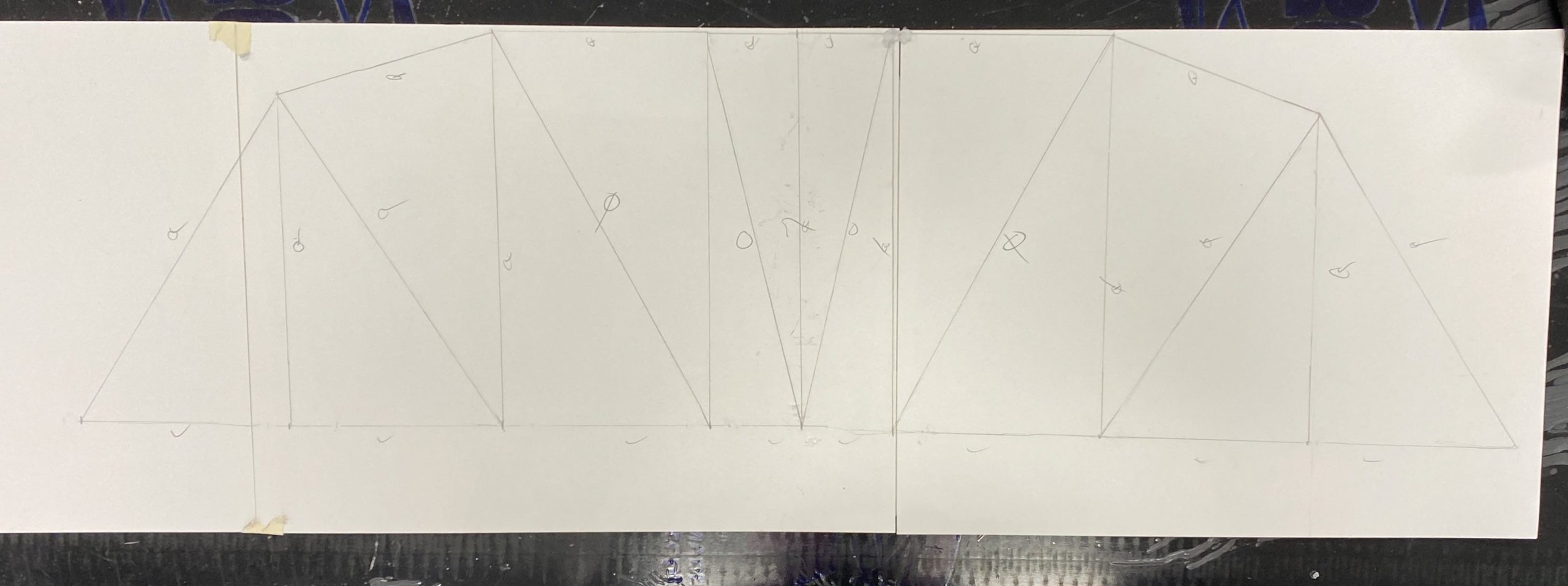
Initial design – we used a statics simulator to test different bridge designs, tension and compression loads, different types of ends (pinned, rolling) and more. This is what we decided on, measured to scale:
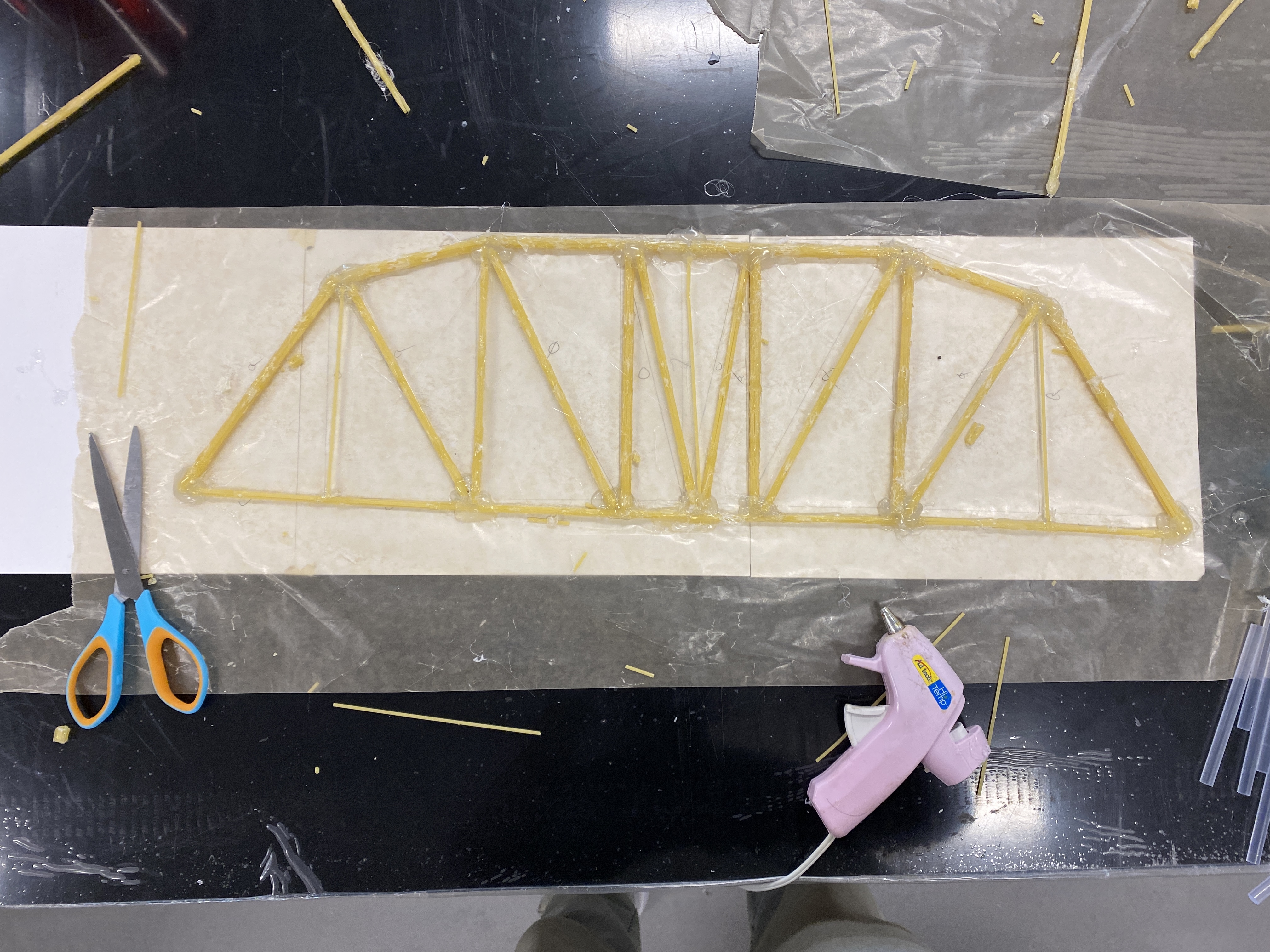
This is the first iteration of the side of our bridge:
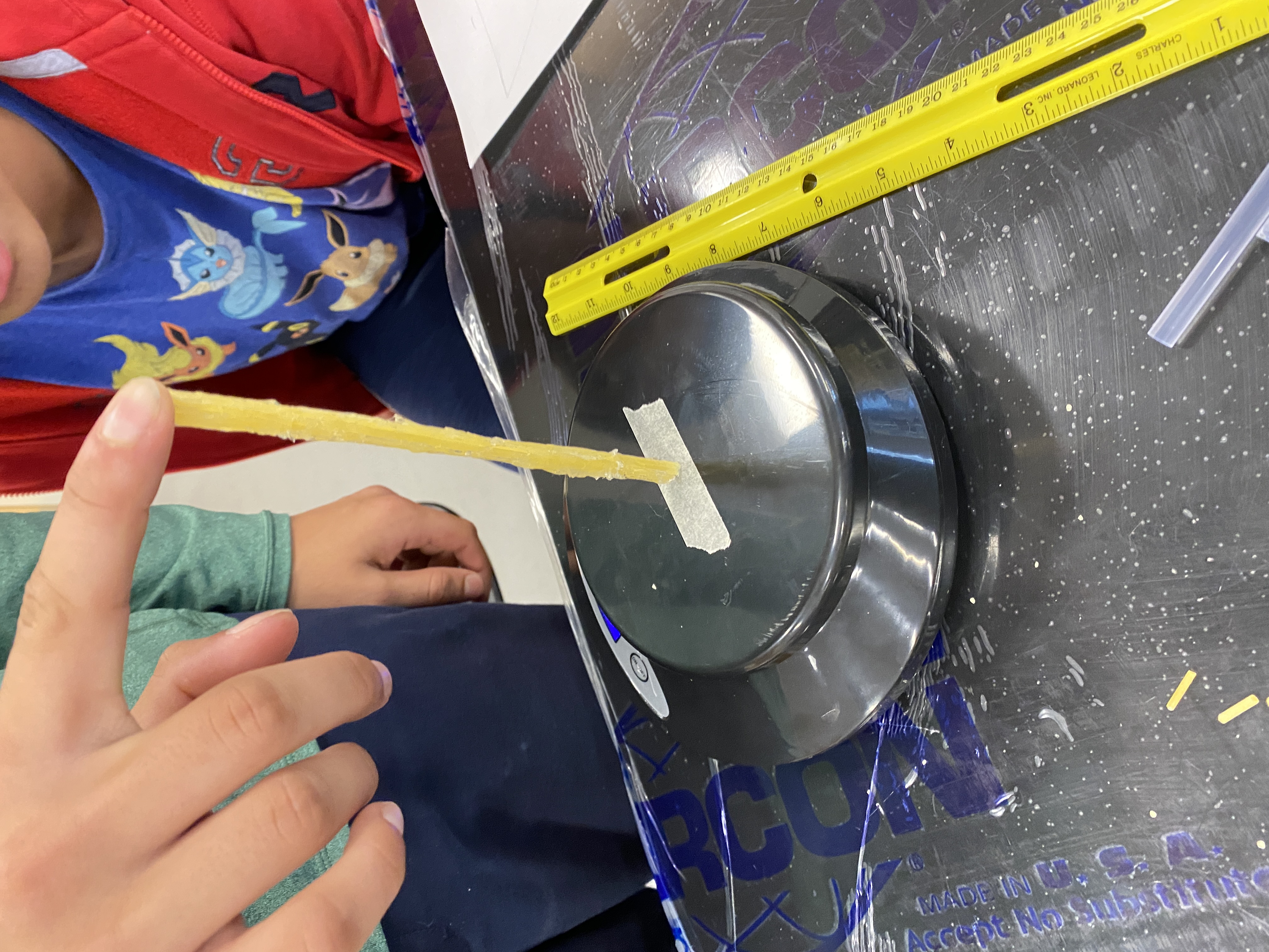
We did some buckling, compression and tension tests using a scale to determine the most efficient amount of spaghetti to have in one beam:
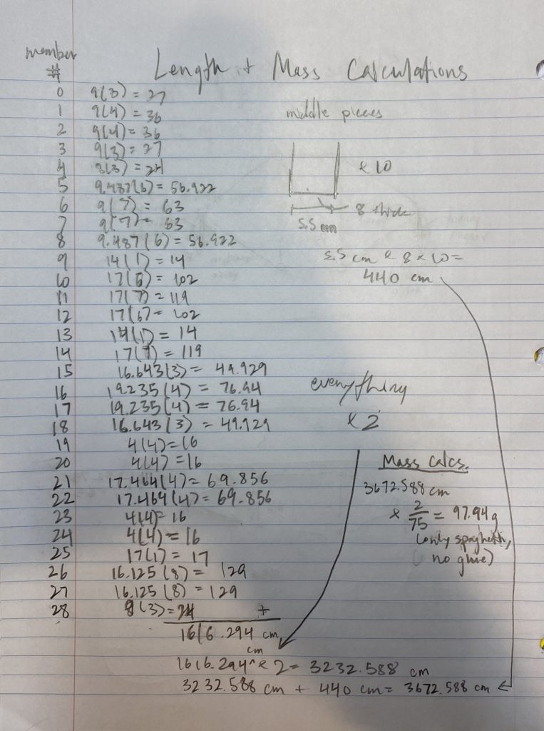
We did some calculations to determine the mass of our bridge with our current design and amount of spaghetti:
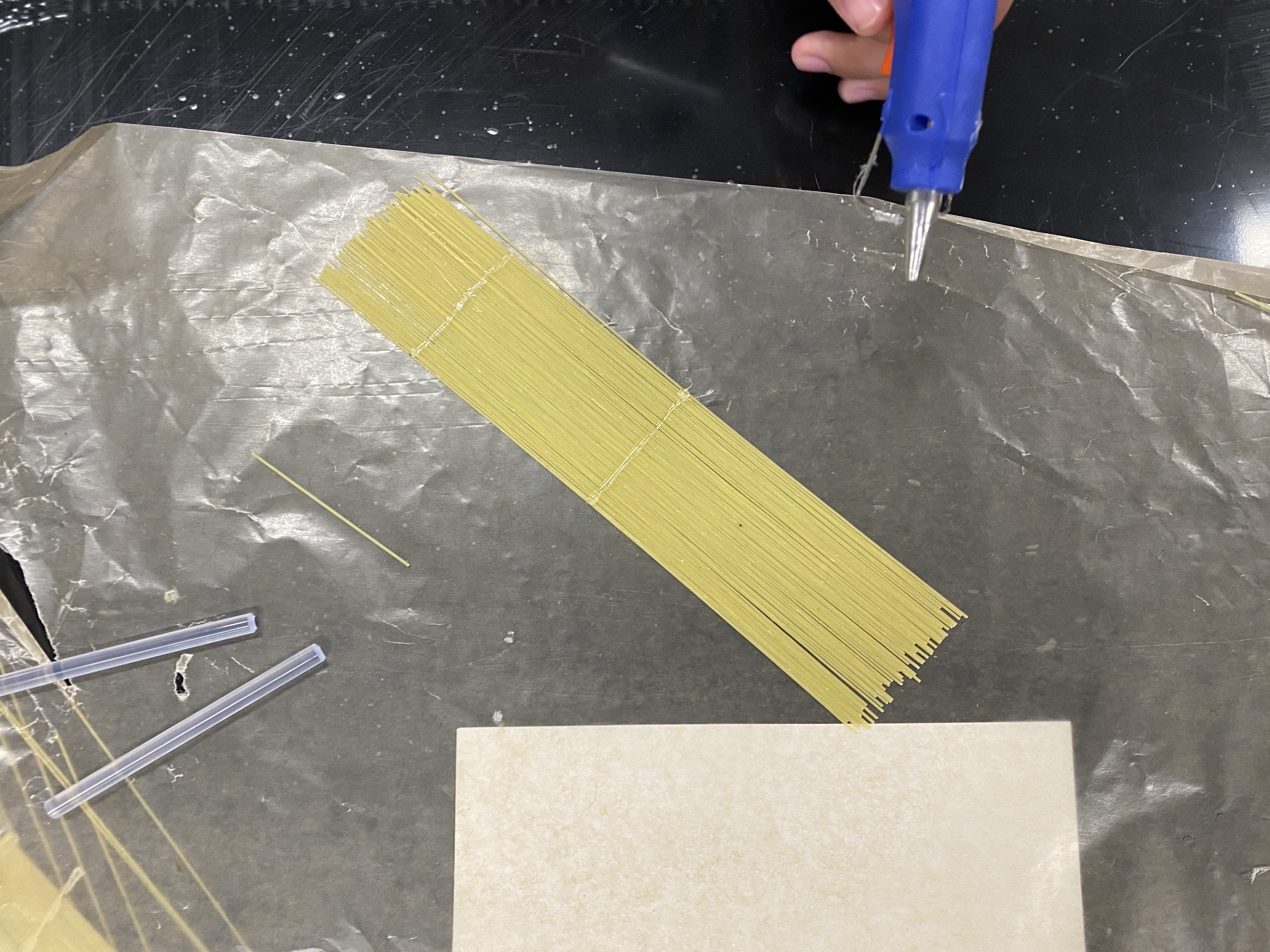
More process photos of making the floor of our bridge, using angel hair spaghetti to use the least amount of mass:
This is was the final build of our bridge:
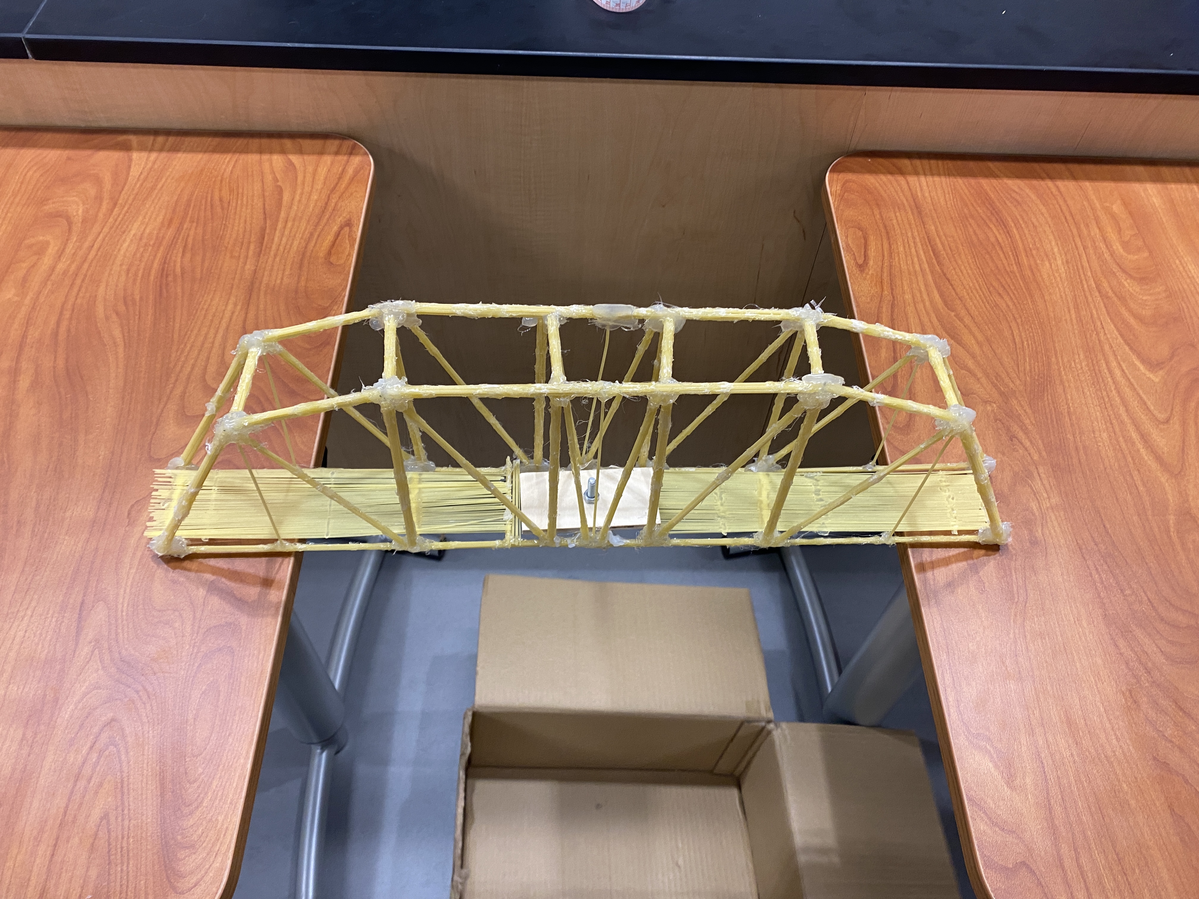
Our bridge did significantly better than all the other teams because it was lightweight by using a minimal amount of hot glue, not too overcomplicated or large, and best handled the force in every static member.
Recorder-Playing Robot
For this project, I worked with one other peer as part of the ESAP program. Below is the documentation for our instrument, including electronics, code, recorder setup and design.
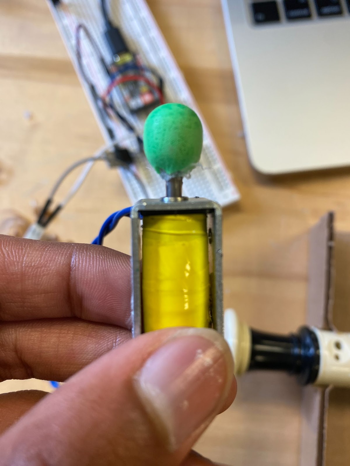

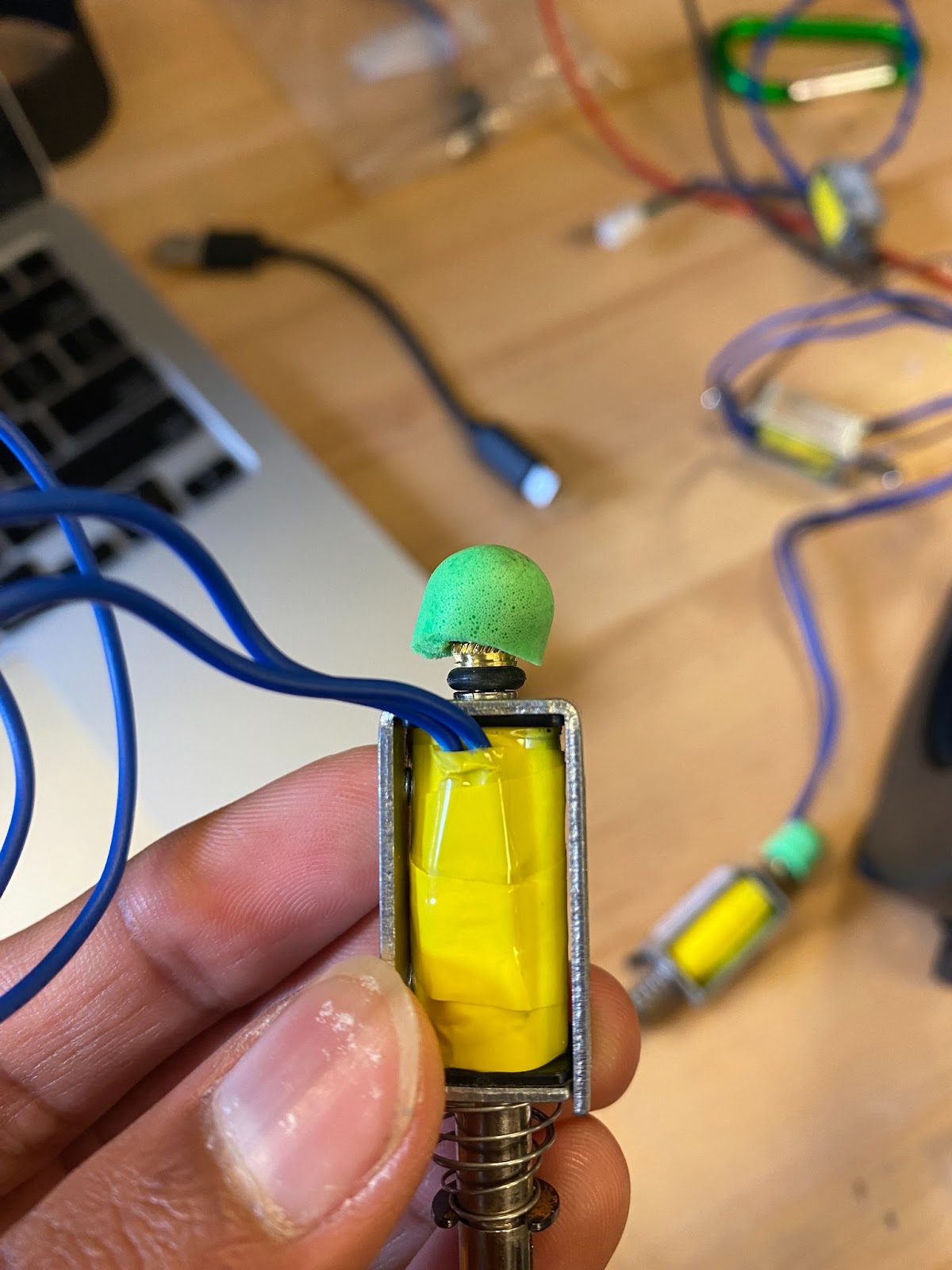
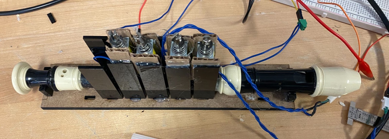
Above are different ways ear plugs were attached to the solenoid plumbers, of which the leftmost worked most successfully because the earplug had the most surface area contacting the solenoid.
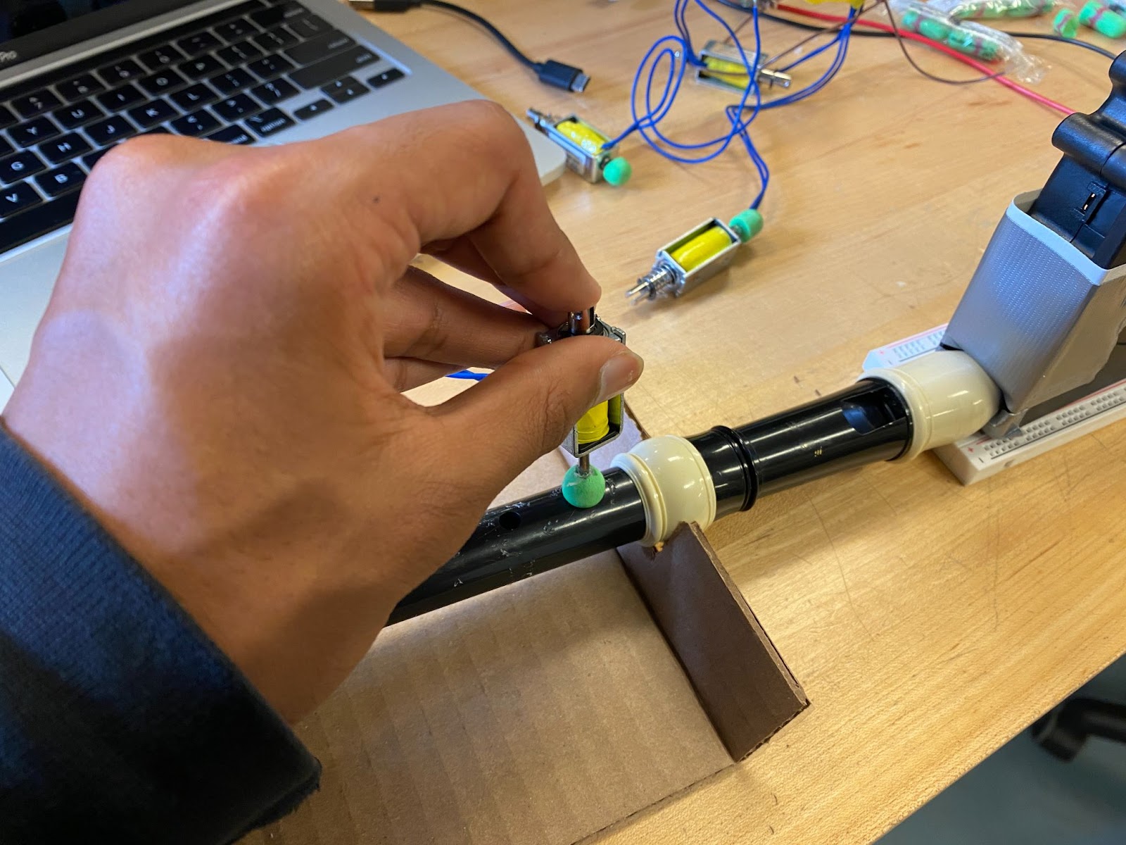
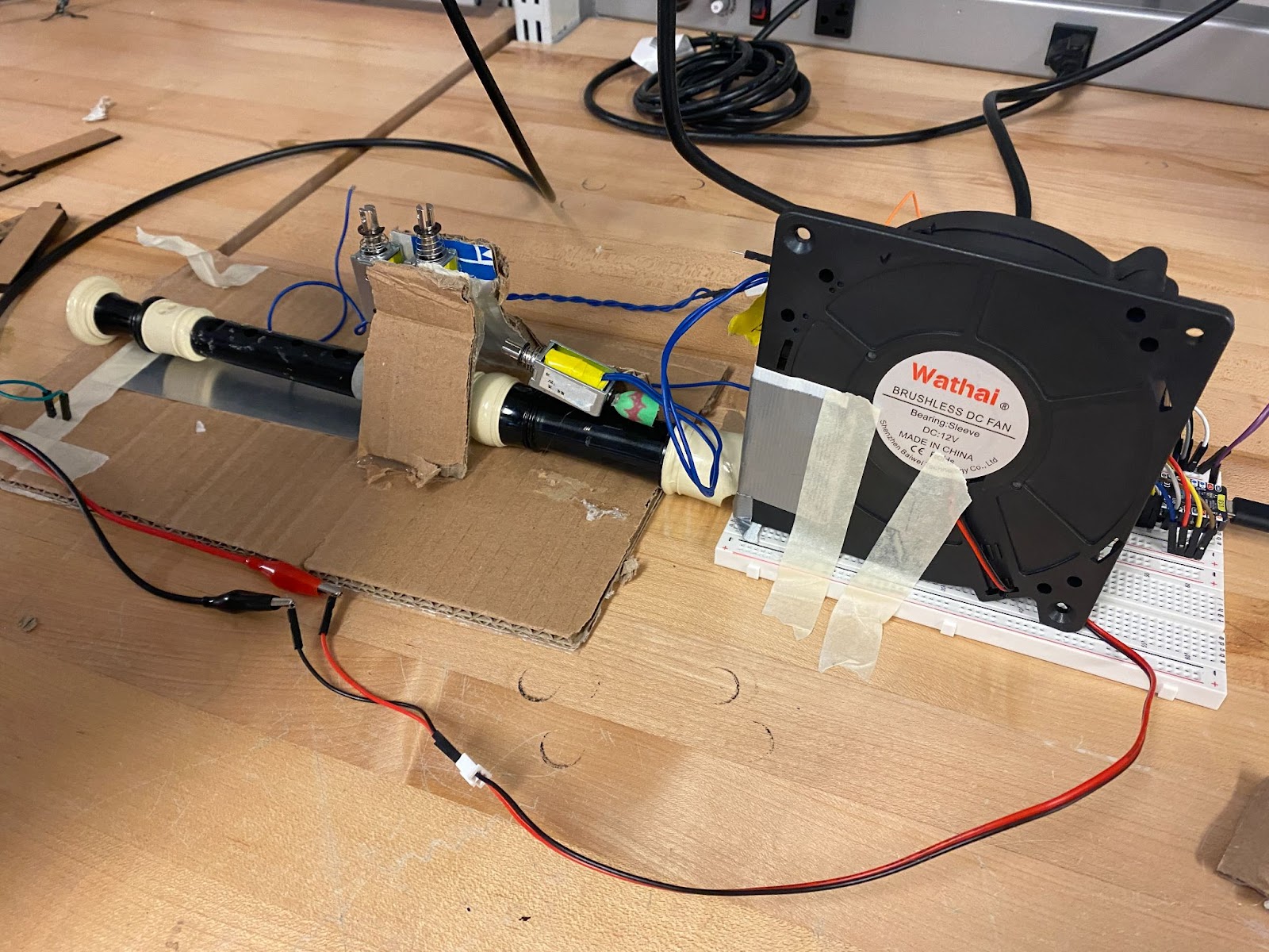

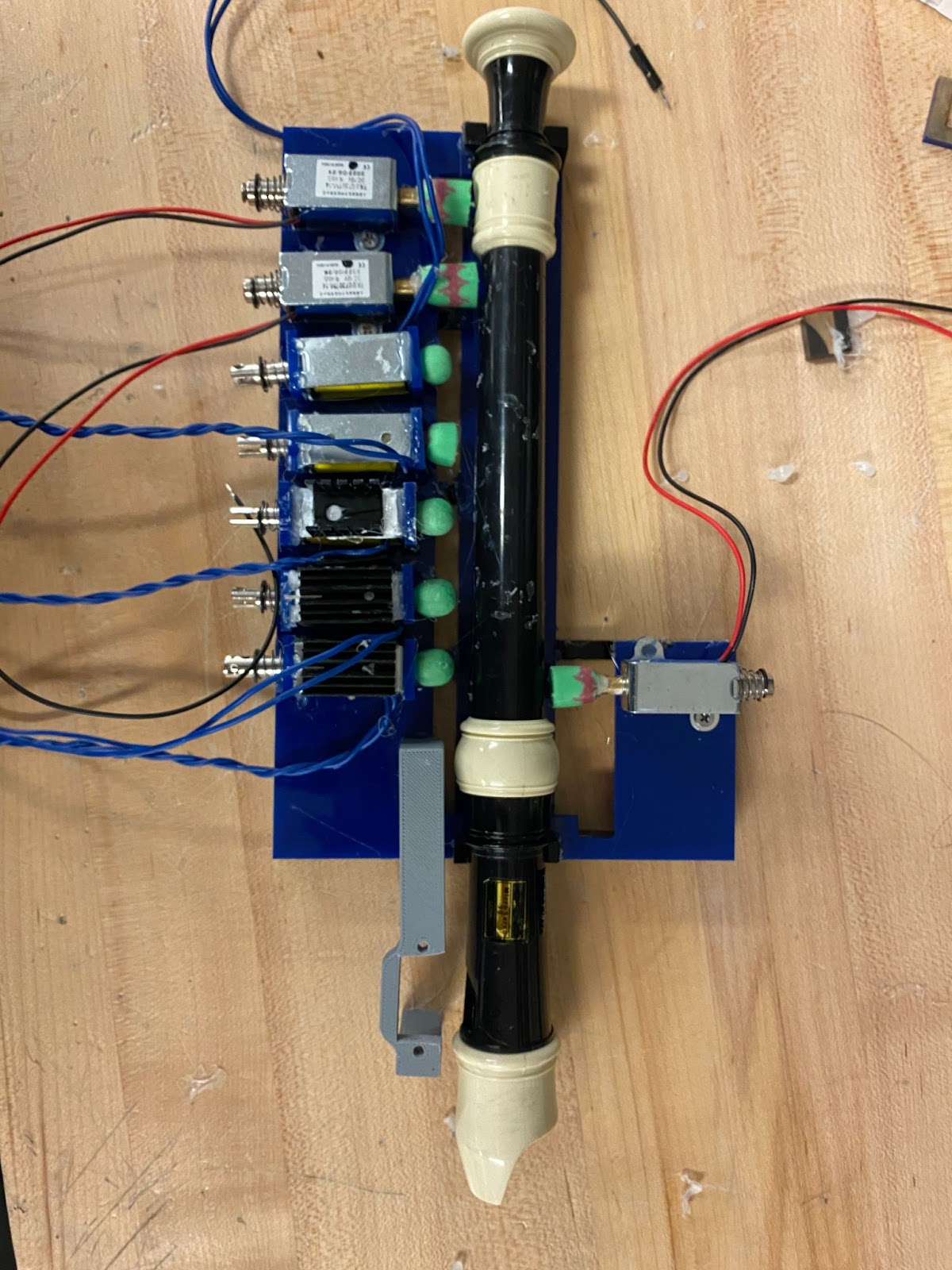
These are photos of early prototyping and testing with solenoids. The fan was first duct taped in the shape of the recorder mouth to seal the airway, and turned on using a power supply. The second setup is a laser cut design made in CAD and then fabricated and assembled into hot glue and press fit pieces. The port expander was inserted in our circuit, and this is where our electrical problems began.
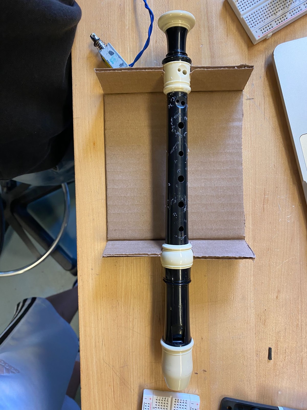
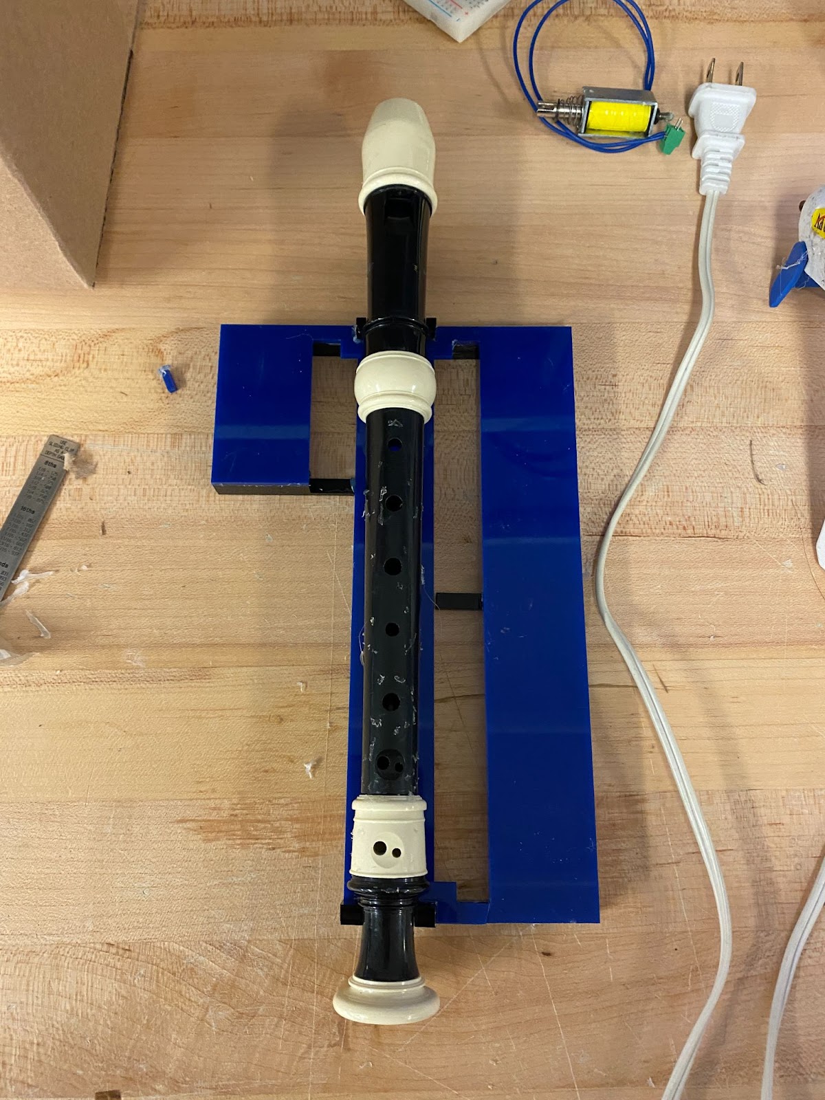
We were content with our design at the time, but I later realized that the thumb hole was inaccessible. There were some notes that required the thumb hole to be opened and closed, so our design had to be remade so that the recorder was positioned sideways to access both sides.
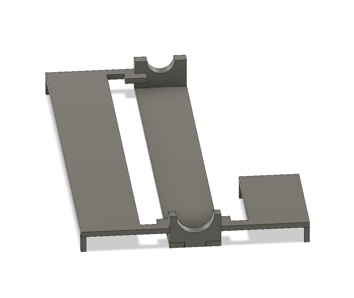
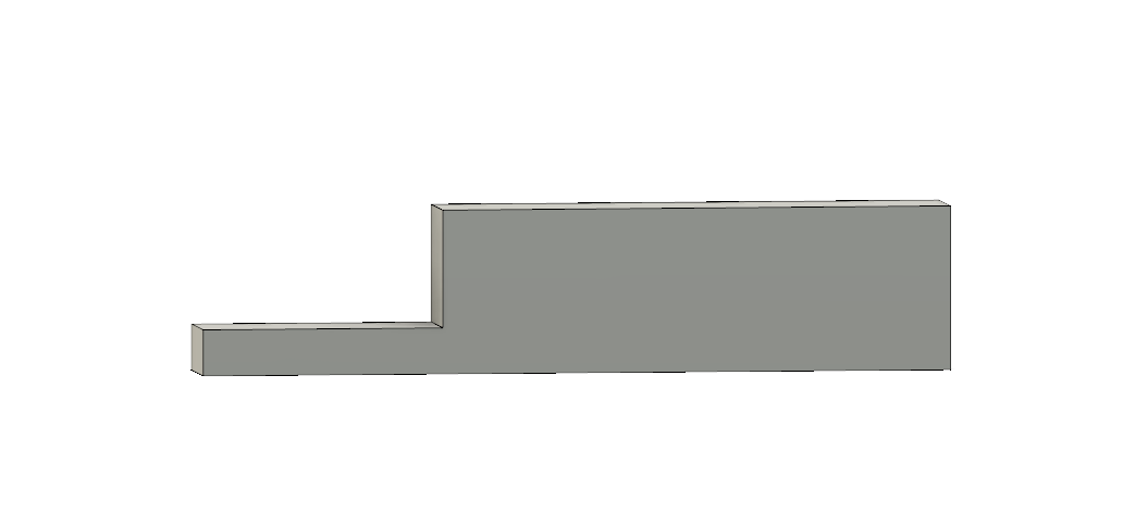
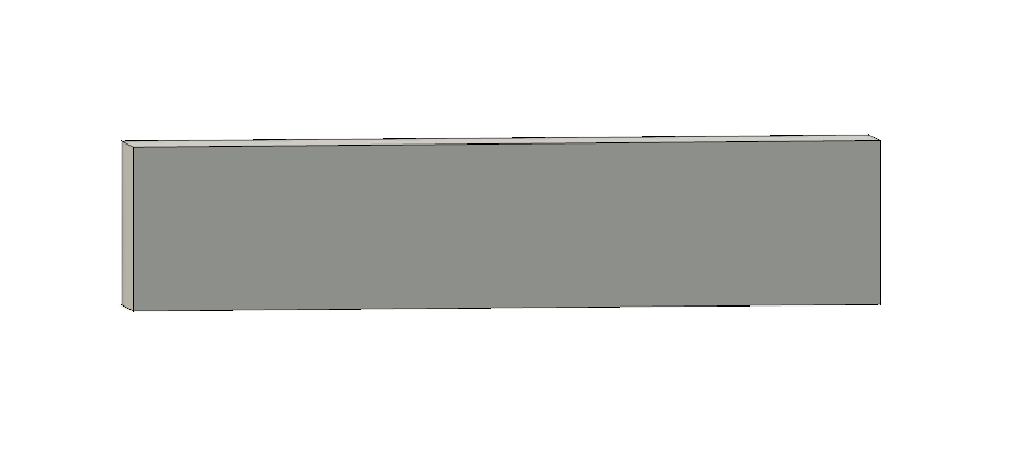
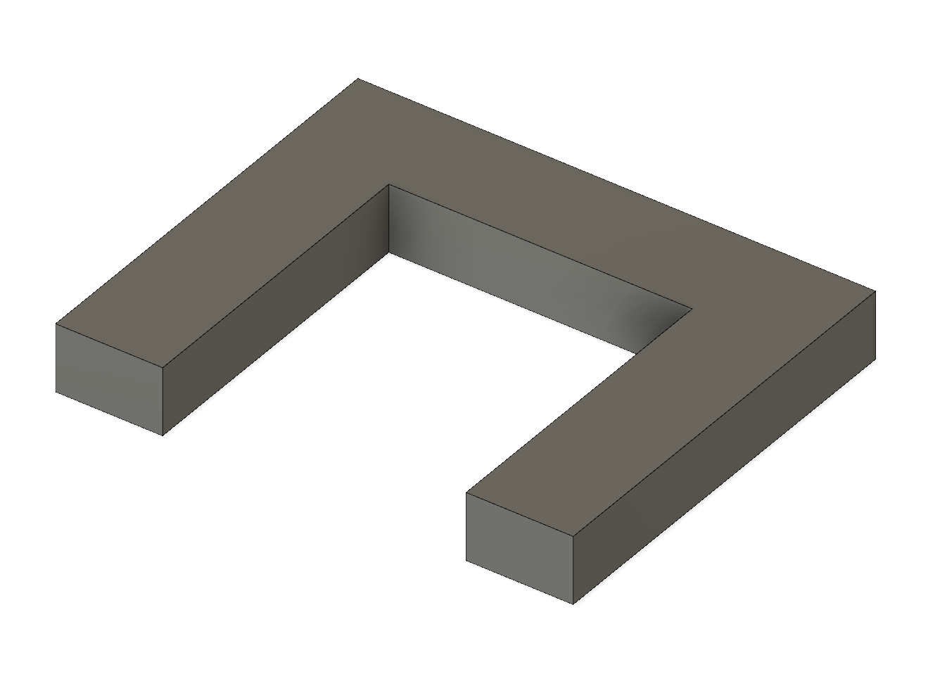
After originally assembling the recorder setup, the smaller flat piece along the side was not connected to the main recorder plate, the support legs were too small with too little surface area, and the middle of the long plate was bending at the center, requiring more support, so I designed additional pieces to do that.
Below is an image of our final design:
It was extremely difficult to attach solenoids in an easy manner with the way I designed the plates, not leaving any room for press fit attachments, which was an oversight on my part and led to significant work being done to find a solution. I could directly attach the solenoids using hot glue because when they get hot, the glue would melt and the solenoid would move out of place. So I had to design some small pieces to keep the solenoid from moving in any direction and minimize use of hot glue.

The final part of our design was adding a mechanism to silence the recorder, for which we used a servo.
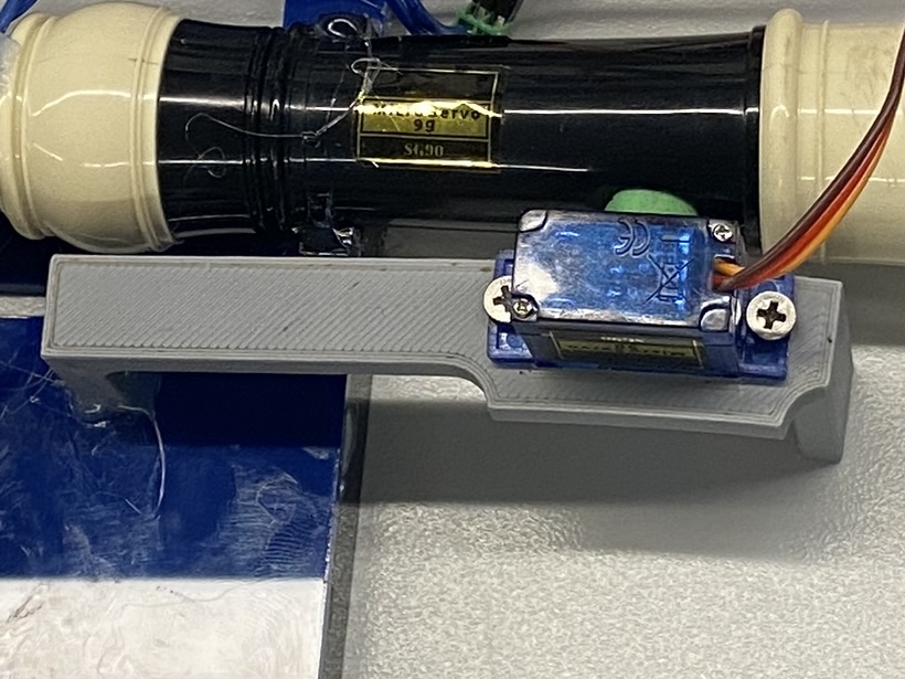
We attached an ear plug to it to act as a plug for the whistle, and wrote some code to actuate it:
#define PWMCHANNEL 1
#define ONEmsCOUNTS ((1<<12)*50/1000)
#define servoPin 4


int minCounts;
int maxCounts;


void setup() {
// put your setup code here, to run once:
ledcSetup(PWMCHANNEL, 50, 12);
ledcAttachPin(servoPin, PWMCHANNEL);
minCounts = 1*ONEmsCOUNTS;
maxCounts = 1.8*ONEmsCOUNTS;


}


void loop() {


for (int i = minCounts; i < maxCounts; i+=5) {
ledcWrite(PWMCHANNEL, i);
delay(20);
}
for (int i = maxCounts; i > minCounts; i-=5) {
ledcWrite(PWMCHANNEL, i);
delay(20);
}


}
We did some testing to find the right range of movement that gave us enough rotation to close the recorder completely, which was a 1.8ms signal.
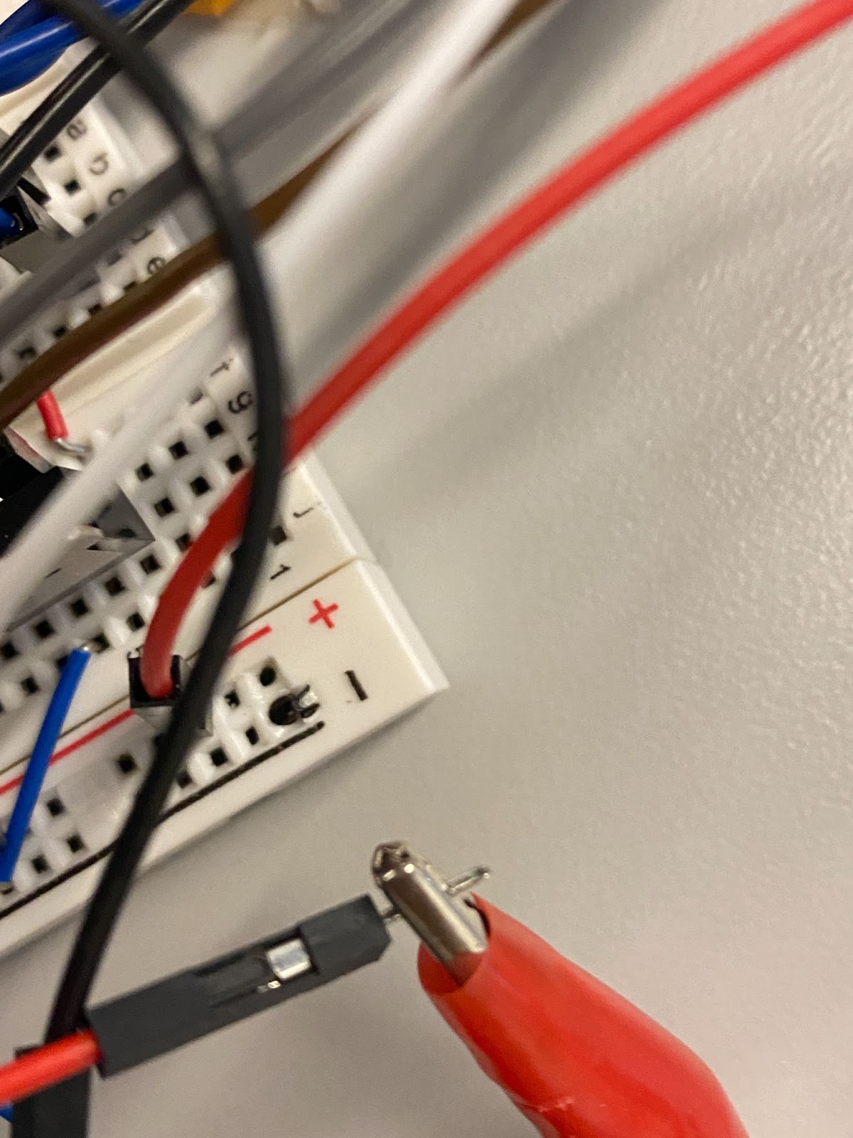
We also added heat syncs to reduce the temperature of our solenoids. However, during this whole process, there were also significant electrical issues. For many days, our port expander did not work. At least, it was unresponsive, even though the wiring should have been correct. However after redoing it using color coded wires for 3.3V, GND, and signal, it started working (picture displayed earlier in this document).
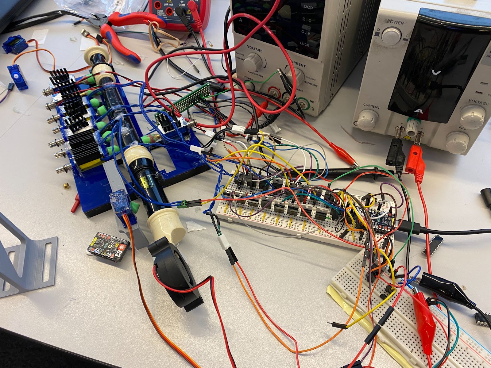
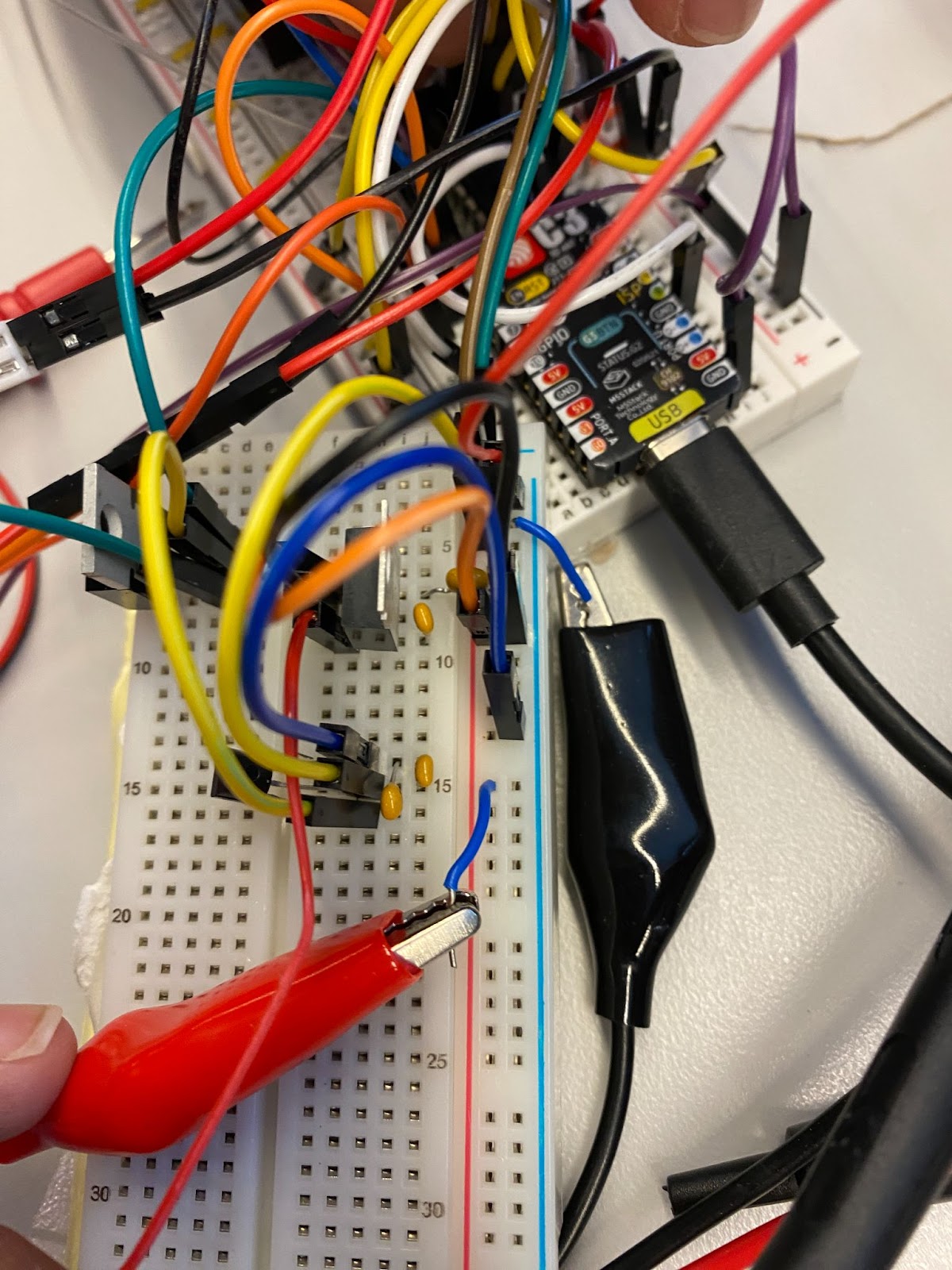
But this only worked with one solenoid, and when at least two were used, our electronics stopped working. We found that there was not enough supplied voltage from the expander into our MOSFETs and then solenoids, but we didn’t know why. This became the bane of our existence, and we wired and rewired things multiple times. Eventually, an extra row of transistors were utilized to amplify voltage and it started working (for the most part). Below is a picture of our circuitry (I know, so beautiful).

Glaring issues would start to appear the next day when testing all solenoids at once using the following code:
#include <Adafruit_MCP23X08.h>
Adafruit_MCP23X08 mcp;


#define solenoid1 0
#define solenoid2 1
#define solenoid3 2
#define solenoid4 3
#define solenoid5 4
#define solenoid6 5
#define solenoid7 6
#define solenoidT 7
#define servo1 4


#define PWMCHANNEL 1
#define ONEms_COUNTS ((1<<12)*50/1000)


int minCounts;
int maxCounts;


void setup() {
// put your setup code here, to run once:
Serial.begin(115200);


Wire.setPins(8,9);
if (!mcp.begin_I2C(0x22,&Wire)) {
Serial.println("Error.");
while (1);
}


mcp.pinMode(solenoid1, OUTPUT); // port expander pin mode setting (to establish output signal)
mcp.pinMode(solenoid2, OUTPUT);
mcp.pinMode(solenoid3, OUTPUT);
mcp.pinMode(solenoid4, OUTPUT);
mcp.pinMode(solenoid5, OUTPUT);
mcp.pinMode(solenoid6, OUTPUT);
mcp.pinMode(solenoid7, OUTPUT);
mcp.pinMode(solenoidT, OUTPUT);


ledcSetup(1, 50, 12); // servo PWM setup
ledcAttachPin(servo1, PWMCHANNEL);
minCounts = 1*ONEms_COUNTS;
maxCounts = 1.8*ONEms_COUNTS;
}


void loop() {
// put your main code here, to run repeatedly:
G();
delay(1500);
A();
delay(1500);
ASharp();
delay(1500);
C();
delay(1500);
D();
delay(1500);
E();
delay(1500);
eff();
delay(1500);
// allOn();
// delay(3000);
stop();
delay(2000);
}


void allOn() {
ledcWrite(PWMCHANNEL, minCounts);
mcp.digitalWrite(solenoidT, HIGH);
mcp.digitalWrite(solenoid1, HIGH);
mcp.digitalWrite(solenoid2, HIGH);
mcp.digitalWrite(solenoid3, HIGH);
mcp.digitalWrite(solenoid4, HIGH);
mcp.digitalWrite(solenoid5, HIGH);
mcp.digitalWrite(solenoid6, HIGH);
mcp.digitalWrite(solenoid7, HIGH);


Serial.println("All solenoids on");
}


void G() {
ledcWrite(PWMCHANNEL, minCounts);
mcp.digitalWrite(solenoidT, HIGH);


mcp.digitalWrite(solenoid1, HIGH);
mcp.digitalWrite(solenoid2, HIGH);
mcp.digitalWrite(solenoid3, HIGH);
mcp.digitalWrite(solenoid4, LOW);
mcp.digitalWrite(solenoid5, LOW);
mcp.digitalWrite(solenoid6, LOW);
mcp.digitalWrite(solenoid7, LOW);
Serial.println("G4");
}


void A() {
ledcWrite(PWMCHANNEL, minCounts);
mcp.digitalWrite(solenoidT, HIGH);


mcp.digitalWrite(solenoid1, HIGH);
mcp.digitalWrite(solenoid2, HIGH);
mcp.digitalWrite(solenoid3, LOW);
mcp.digitalWrite(solenoid4, LOW);
mcp.digitalWrite(solenoid5, LOW);
mcp.digitalWrite(solenoid6, LOW);
mcp.digitalWrite(solenoid7, LOW);
Serial.println("A4");
}


void ASharp() {
ledcWrite(PWMCHANNEL, minCounts);
mcp.digitalWrite(solenoidT, HIGH);


mcp.digitalWrite(solenoid1, HIGH);
mcp.digitalWrite(solenoid2, LOW);
mcp.digitalWrite(solenoid3, HIGH);
mcp.digitalWrite(solenoid4, LOW);
mcp.digitalWrite(solenoid5, HIGH);
mcp.digitalWrite(solenoid6, HIGH);
mcp.digitalWrite(solenoid7, LOW);


Serial.println("A#4");
}


void C() {
ledcWrite(PWMCHANNEL, minCounts);
mcp.digitalWrite(solenoidT, HIGH);


mcp.digitalWrite(solenoid1, HIGH);
mcp.digitalWrite(solenoid2, HIGH);
mcp.digitalWrite(solenoid3, HIGH);
mcp.digitalWrite(solenoid4, HIGH);
mcp.digitalWrite(solenoid5, HIGH);
mcp.digitalWrite(solenoid6, HIGH);
mcp.digitalWrite(solenoid7, HIGH);


Serial.println("C5");
}


void D() {
ledcWrite(PWMCHANNEL, minCounts);
mcp.digitalWrite(solenoidT, HIGH);


mcp.digitalWrite(solenoid1, HIGH);
mcp.digitalWrite(solenoid2, HIGH);
mcp.digitalWrite(solenoid3, HIGH);
mcp.digitalWrite(solenoid4, HIGH);
mcp.digitalWrite(solenoid5, HIGH);
mcp.digitalWrite(solenoid6, HIGH);
mcp.digitalWrite(solenoid7, LOW);


Serial.println("D5");
}


void E() {
ledcWrite(PWMCHANNEL, minCounts);
mcp.digitalWrite(solenoidT, HIGH);


mcp.digitalWrite(solenoid1, HIGH);
mcp.digitalWrite(solenoid2, HIGH);
mcp.digitalWrite(solenoid3, HIGH);
mcp.digitalWrite(solenoid4, HIGH);
mcp.digitalWrite(solenoid5, HIGH);
mcp.digitalWrite(solenoid6, LOW);
mcp.digitalWrite(solenoid7, LOW);


Serial.println("E5");
}


void eff() {
ledcWrite(PWMCHANNEL, minCounts);
mcp.digitalWrite(solenoidT, HIGH);
mcp.digitalWrite(solenoid1, HIGH);
mcp.digitalWrite(solenoid2, HIGH);
mcp.digitalWrite(solenoid3, HIGH);
mcp.digitalWrite(solenoid4, HIGH);
mcp.digitalWrite(solenoid5, LOW);
mcp.digitalWrite(solenoid6, HIGH);
mcp.digitalWrite(solenoid7, HIGH);


Serial.println("F5");
}


void stop() {
ledcWrite(PWMCHANNEL, maxCounts);
Serial.println("Stopping note");
}
Problems with current draw popped up, burning our breadboard and important electronics.

This is when we noticed that our power supply (we had two, but one for all solenoids and one for our 5V servo) was constantly hitting 5A and constant current, requiring a pivot to using two power supplies to power a couple solenoids each.
We added a voltage regulator that stepped the 12V down to 5V for our servo motor and some other transistors to test with our solenoids, due to their inconsistency and a specific couple not even actuating when a signal was sent to them. This somewhat helped, and from then, code became the focus.
Below is our final code with WiFi incorporated and both songs:
#include <Adafruit_MCP23X08.h>
#include <WiFi.h>
#include <WiFiUdp.h>
WiFiUDP UDPTestServer;
Adafruit_MCP23X08 mcp;


#define solenoid1 0
#define solenoid2 1
#define solenoid3 2
#define solenoid4 3
#define solenoid5 4
#define solenoid6 5
#define solenoid7 6
#define solenoidT 7
#define servo1 4
#define mic 5


#define PWMCHANNEL 1
#define ONEms_COUNTS ((1<<12)*50/1000)


uint32_t timebase;
int minCounts;
int maxCounts;
int currentIndex = 0;
int currentIndex2 = 0;
int delayTime = 10;


// Notes for We Care a Lot by Faith No More
int midiNote[] = {81, 82, 84, 82, 81, 82, 84, 82, 81, 82, 84, 82, 81, 82, 84, 86, 81, 79, 79, 81, 79, 81, 79, 81, 79, 81, 82, 84, 82, 81, 82, 84, 82, 81, 82, 84, 82, 81, 82, 84, 86, 81, 79, 79, 81, 79, 81, 79, 81, 79, 81, 79, 79, 81, 79, 81, 79, 81, 79, 81, 82, 84, 82, 81, 82, 84, 86, 81, 79, 79, 81, 79, 81, 79, 81, 79, 81, 79, 79, 81, 79, 81, 79, 81, 79, 81, 79, 79, 81, 79, 81, 79, 81, 79};
float startTime[] = {22.0184, 24.2202, 26.422, 28.6239, 30.8257, 33.0275, 35.2294, 37.4312, 39.633, 41.8349, 44.0367, 46.2386, 48.4404, 50.6422, 52.8441, 55.0459, 59.4496, 61.6514, 63.0276, 63.8532, 66.0551, 68.2569, 70.4588, 72.6606, 74.8624, 77.0643, 79.2661, 81.4679, 83.6698, 85.8716, 88.0734, 90.2753, 92.4771, 94.6789, 96.8808, 99.0826, 101.2845, 103.4863, 105.6881, 107.89, 110.0918, 114.4955, 116.6973, 118.0735, 118.8991, 121.101, 123.3028, 125.5047, 127.7065, 129.9083, 132.1102, 134.312, 135.6881, 136.5138, 138.7157, 140.9175, 143.1193, 145.3212, 147.523, 167.3395, 169.5414, 171.7432, 173.945, 176.1469, 178.3487, 180.5506, 182.7524, 187.1561, 189.3579, 190.734, 191.5597, 193.7616, 195.9634, 198.1652, 200.3671, 202.5689, 204.7707, 206.9726, 208.3487, 209.1744, 211.3763, 213.5781, 215.7799, 217.9818, 220.1836, 222.3854, 224.5873, 225.9634, 226.7891, 228.9909, 231.1928, 233.3946, 235.5965, 237.7983};
float endTime[] = {24.219, 26.4209, 28.6227, 30.8246, 33.0264, 35.2282, 37.4301, 39.6319, 41.8337, 44.0356, 46.2374, 48.4392, 50.6411, 52.8429, 55.0448, 57.2466, 61.6503, 63.0264, 63.8521, 66.0539, 68.2558, 70.4576, 72.6594, 74.8613, 77.0631, 79.2649, 81.4668, 83.6686, 85.8705, 88.0723, 90.2741, 92.476, 94.6778, 96.8796, 99.0815, 101.2833, 103.4851, 105.687, 107.8888, 110.0907, 112.2925, 116.6962, 118.0723, 118.898, 121.0998, 123.3017, 125.5035, 127.7053, 129.9072, 132.109, 134.3108, 135.687, 136.5127, 138.7145, 140.9164, 143.1182, 145.32, 147.5219, 149.7237, 169.5402, 171.7421, 173.9439, 176.1457, 178.3476, 180.5494, 182.7512, 184.9531, 189.3567, 190.7329, 191.5586, 193.7604, 195.9623, 198.1641, 200.3659, 202.5678, 204.7696, 206.9714, 208.3476, 209.1733, 211.3751, 213.5769, 215.7788, 217.9806, 220.1825, 222.3843, 224.5861, 225.9623, 226.788, 228.9898, 231.1916, 233.3935, 235.5953, 237.7971, 239.999};


int maxNotes = sizeof(midiNote)/sizeof(int);


// Notes for Demons by Imagine Dragons
int midiNote2[] = {89,88,89,84,89,88,89,84,89,88,89,84,89,88,89,84,89,88,89,86,89,88,89,86,89,88,89,86,89,88,89,84,89,88,89,84,89,88,89,84,89,88,89,84,89,88,89,84,89,88,89,86,89,88,89,86,89,88,89,86,89,88,89,84,89,88,89,84,89,88,89,84,89,88,89,84,89,88,89,84,89,88,89,86,89,88,89,86,89,88,89,86,89,88,89,84,89,88,89,84,89,88,89,84,89,88,89,84,89,88,89,84,89,88,89,86,89,88,89,86,89,88,89,86,89,88,89,84,89,88,89,84,89,88,89,84,89,88,89,84,89,88,89,84,89,88,89,86,89,88,89,86,89,88,89,86,89,88,89,84,89,88,89,84,89,88,89,84,89,88,89,84,89,88,89,84,89,88,89,86,89,88,89,86,89,88,89,86,89,88,89,84,89,88,89,84,89,88,89,84,89,88,89,84,89,88,89,84,89,88,89,86,89,88,89,86,89,88,89,86,89,88,89,84,89,88,89,84,89,88,89,84,89,88,89,84,89,88,89,84,89,88,89,84,89,88,89,84,89,88,89,84,89,88,89,84,89,88,89,84,89,88,89,84,89,88,89,84,89,88,89,84,89,88,89,84,89,88,89,84,89,88,89,84,89,88,89,84,89,88,89,84,89,88,89,84,89,88,89,84,89,88,89,84,89,88,89,84,89,88,89,84,89,88,89,84,89,88,89,84,89,88,89,84,89,88,89,84,89,88,89,84,89,88,89,84,89,88,89,84,89,88,89,84,89,88,89,84,89,88,89,84,89,88,89,84,89,88,89,84,89,88,89,84,89,88,89,84,89,88,89,84,89,88,89,84,89,88,89,84,89,88,89,84,89,88,89,84,89,88,89,84,89,88,89,84,89,88,89,84,89,88,89,84,89,88,89,84,89,88,89,84,89,88,89,84,89,88,89,84,89,88,89,84,89,88,89,84,89,88,89,84,89,88,89,84,89,88,89,84,89,88,89,84,89,88,89,84,89,88,89,84,89,88,89,84,89,88,89,84,89,88,89,84,89,88,89,84,89,88,89,84,89,88,89,84,89,88,89,84};
float startTime2[] = {2.3,2.6,2.9,3.2,3.5,3.9,4.2,4.5,4.8,5.2,5.5,5.8,6.1,6.5,6.8,7.1,7.4,7.7,8.1,8.4,8.7,9,9.4,9.7,10,10.3,10.6,11,11.3,11.6,11.9,12.3,12.6,12.9,13.2,13.5,13.9,14.2,14.5,14.8,15.2,15.5,15.8,16.1,16.5,16.8,17.1,17.4,17.7,18.1,18.4,18.7,19,19.4,19.7,20,20.3,20.6,21,21.3,21.6,21.9,22.3,22.6,22.9,23.2,23.5,23.9,24.2,24.5,24.8,25.2,25.5,25.8,26.1,26.5,26.8,27.1,27.4,27.7,28.1,28.4,28.7,29,29.4,29.7,30,30.3,30.6,31,31.3,31.6,31.9,32.3,32.6,32.9,33.2,33.5,33.9,34.2,34.5,34.8,35.2,35.5,35.8,36.1,36.5,36.8,37.1,37.4,37.7,38.1,38.4,38.7,39,39.4,39.7,40,40.3,40.6,41,41.3,41.6,41.9,42.3,42.6,42.9,43.2,43.5,43.9,44.2,44.5,44.8,45.2,45.5,45.8,46.1,46.5,46.8,47.1,47.4,47.7,48.1,48.4,48.7,49,49.4,49.7,50,50.3,50.6,51,51.3,51.6,51.9,52.3,52.6,52.9,53.2,53.5,53.9,54.2,54.5,54.8,55.2,55.5,55.8,56.1,56.5,56.8,57.1,57.4,57.7,58.1,58.4,58.7,59,59.4,59.7,60,60.3,60.6,61,61.3,61.6,61.9,62.3,62.6,62.9,63.2,63.5,63.9,64.2,64.5,64.8,65.2,65.5,65.8,66.1,66.5,66.8,67.1,67.4,67.7,68.1,68.4,68.7,69,69.4,69.7,70,70.3,70.6,71,71.3,71.6,71.9,72.3,72.6,72.9,73.2,73.5,73.9,74.2,74.5,74.8,75.2,75.5,75.8,76.1,76.5,76.8,77.1,77.4,77.7,78.1,78.4,78.7,79,79.4,79.7,80,80.3,80.6,81,81.3,81.6,81.9,82.3,82.6,82.9,83.2,83.5,83.9,84.2,84.5,84.8,85.2,85.5,85.8,86.1,86.5,86.8,87.1,87.4,87.7,88.1,88.4,88.7,89,89.4,89.7,90,90.3,90.6,91,91.3,91.6,91.9,92.3,92.6,92.9,93.2,93.5,93.9,94.2,94.5,94.8,95.2,95.5,95.8,96.1,96.5,96.8,97.1,97.4,97.7,98.1,98.4,98.7,99,99.4,99.7,100,100.3,100.6,101,101.3,101.6,101.9,102.3,102.6,102.9,103.2,103.5,103.9,104.2,104.5,104.8,105.2,105.5,105.8,106.1,106.5,106.8,107.1,107.4,107.7,108.1,108.4,108.7,109,109.4,109.7,110,110.3,110.6,111,111.3,111.6,111.9,112.3,112.6,112.9,113.2,113.5,113.9,114.2,114.5,114.8,115.2,115.5,115.8,116.1,116.5,116.8,117.1,117.4,117.7,118.1,118.4,118.7,119,119.4,119.7,120,120.3,120.6,121,121.3,121.6,121.9,122.3,122.6,122.9,123.2,123.5,123.9,124.2,124.5,124.8,125.2,125.5,125.8,126.1,126.5,126.8,127.1,127.4,127.7,128.1,128.4,128.7,129,129.4,129.7,130,130.3,130.6,131,131.3,131.6,131.9,132.3,132.6,132.9,133.2,133.5,133.9,134.2,134.5,134.8,135.2,135.5,135.8,136.1,136.5,157.4,157.7,158.1,158.4,158.7,159,159.4,159.7,160,160.3,160.6,161,161.3,161.6,161.9,162.3,162.6,162.9,163.2,163.5,163.9,164.2,164.5,164.8,165.2,165.5,165.8,166.1,166.5,166.8,167.1,167.4,167.7,168.1,168.4,168.7,169,169.4,169.7,170,170.3,170.6,171,171.3,171.6,171.9,172.3,172.6,172.9,173.2,173.5,173.9,174.2,174.5,174.8,175.2,175.5,175.8,176.1,176.5,176.8,177.1,177.4};
float endTime2[] = {2.6,2.9,3.2,3.5,3.9,4.2,4.5,4.8,5.2,5.5,5.8,6.1,6.5,6.8,7.1,7.4,7.7,8.1,8.4,8.7,9,9.4,9.7,10,10.3,10.6,11,11.3,11.6,11.9,12.3,12.6,12.9,13.2,13.5,13.9,14.2,14.5,14.8,15.2,15.5,15.8,16.1,16.5,16.8,17.1,17.4,17.7,18.1,18.4,18.7,19,19.4,19.7,20,20.3,20.6,21,21.3,21.6,21.9,22.3,22.6,22.9,23.2,23.5,23.9,24.2,24.5,24.8,25.2,25.5,25.8,26.1,26.5,26.8,27.1,27.4,27.7,28.1,28.4,28.7,29,29.4,29.7,30,30.3,30.6,31,31.3,31.6,31.9,32.3,32.6,32.9,33.2,33.5,33.9,34.2,34.5,34.8,35.2,35.5,35.8,36.1,36.5,36.8,37.1,37.4,37.7,38.1,38.4,38.7,39,39.4,39.7,40,40.3,40.6,41,41.3,41.6,41.9,42.3,42.6,42.9,43.2,43.5,43.9,44.2,44.5,44.8,45.2,45.5,45.8,46.1,46.5,46.8,47.1,47.4,47.7,48.1,48.4,48.7,49,49.4,49.7,50,50.3,50.6,51,51.3,51.6,51.9,52.3,52.6,52.9,53.2,53.5,53.9,54.2,54.5,54.8,55.2,55.5,55.8,56.1,56.5,56.8,57.1,57.4,57.7,58.1,58.4,58.7,59,59.4,59.7,60,60.3,60.6,61,61.3,61.6,61.9,62.3,62.6,62.9,63.2,63.5,63.9,64.2,64.5,64.8,65.2,65.5,65.8,66.1,66.5,66.8,67.1,67.4,67.7,68.1,68.4,68.7,69,69.4,69.7,70,70.3,70.6,71,71.3,71.6,71.9,72.3,72.6,72.9,73.2,73.5,73.9,74.2,74.5,74.8,75.2,75.5,75.8,76.1,76.5,76.8,77.1,77.4,77.7,78.1,78.4,78.7,79,79.4,79.7,80,80.3,80.6,81,81.3,81.6,81.9,82.3,82.6,82.9,83.2,83.5,83.9,84.2,84.5,84.8,85.2,85.5,85.8,86.1,86.5,86.8,87.1,87.4,87.7,88.1,88.4,88.7,89,89.4,89.7,90,90.3,90.6,91,91.3,91.6,91.9,92.3,92.6,92.9,93.2,93.5,93.9,94.2,94.5,94.8,95.2,95.5,95.8,96.1,96.5,96.8,97.1,97.4,97.7,98.1,98.4,98.7,99,99.4,99.7,100,100.3,100.6,101,101.3,101.6,101.9,102.3,102.6,102.9,103.2,103.5,103.9,104.2,104.5,104.8,105.2,105.5,105.8,106.1,106.5,106.8,107.1,107.4,107.7,108.1,108.4,108.7,109,109.4,109.7,110,110.3,110.6,111,111.3,111.6,111.9,112.3,112.6,112.9,113.2,113.5,113.9,114.2,114.5,114.8,115.2,115.5,115.8,116.1,116.5,116.8,117.1,117.4,117.7,118.1,118.4,118.7,119,119.4,119.7,120,120.3,120.6,121,121.3,121.6,121.9,122.3,122.6,122.9,123.2,123.5,123.9,124.2,124.5,124.8,125.2,125.5,125.8,126.1,126.5,126.8,127.1,127.4,127.7,128.1,128.4,128.7,129,129.4,129.7,130,130.3,130.6,131,131.3,131.6,131.9,132.3,132.6,132.9,133.2,133.5,133.9,134.2,134.5,134.8,135.2,135.5,135.8,136.1,136.5,136.8,157.7,158.1,158.4,158.7,159,159.4,159.7,160,160.3,160.6,161,161.3,161.6,161.9,162.3,162.6,162.9,163.2,163.5,163.9,164.2,164.5,164.8,165.2,165.5,165.8,166.1,166.5,166.8,167.1,167.4,167.7,168.1,168.4,168.7,169,169.4,169.7,170,170.3,170.6,171,171.3,171.6,171.9,172.3,172.6,172.9,173.2,173.5,173.9,174.2,174.5,174.8,175.2,175.5,175.8,176.1,176.5,176.8,177.1,177.4,177.7};


int maxNotes2 = sizeof(midiNote2)/sizeof(int);


void setup() {


Serial.begin(115200);
Wire.setPins(8,9);
if (!mcp.begin_I2C(0x22,&Wire)) {
Serial.println("Error.");
while (1);
}
delay(100);
WiFi.begin("TP-Link_E0C8", "52665134");
WiFi.config(IPAddress(192,168,1,93), IPAddress(192,168,1,1), IPAddress(255,255,255,0));


while(WiFi.status() != WL_CONNECTED) {
delay(500);
Serial.print(".");
}


Serial.println("WiFi Connected");


UDPTestServer.begin(2808);


ledcSetup(1, 50, 12); // servo PWM setup
ledcAttachPin(servo1, PWMCHANNEL);
minCounts = 1*ONEms_COUNTS;
maxCounts = 1.8*ONEms_COUNTS;


mcp.pinMode(solenoid1, OUTPUT); // port expander pin mode setting (to establish output signal)
mcp.pinMode(solenoid2, OUTPUT);
mcp.pinMode(solenoid3, OUTPUT);
mcp.pinMode(solenoid4, OUTPUT);
mcp.pinMode(solenoid5, OUTPUT);
mcp.pinMode(solenoid6, OUTPUT);
mcp.pinMode(solenoid7, OUTPUT);
mcp.pinMode(solenoidT, OUTPUT);


pinMode(mic, INPUT);


delay(100);
ledcWrite(PWMCHANNEL, maxCounts);
Serial.println("Setup finished");
}


void loop() {


int packet = getUDPPacket();


if (packet == 1) {
mcp.digitalWrite(solenoidT, HIGH);
mcp.digitalWrite(solenoid1, HIGH);
mcp.digitalWrite(solenoid2, HIGH);
mcp.digitalWrite(solenoid3, HIGH);
mcp.digitalWrite(solenoid4, HIGH);
mcp.digitalWrite(solenoid5, HIGH);
mcp.digitalWrite(solenoid6, HIGH);
mcp.digitalWrite(solenoid7, HIGH);


Serial.println("Played one note");
delay(1000);
}
else if (packet == 2) { // first song: We Care a Lot by Faith No More
Serial.println("Playing WCAL");
delay(startTime[0]*1000);
while(currentIndex < maxNotes - 1) {
playNote();
delay((endTime[currentIndex] - startTime[currentIndex])*1000 - delayTime);
Serial.print("Playing for ");
Serial.print((endTime[currentIndex] - startTime[currentIndex])*1000 - delayTime);
stopNote();
delay((startTime[currentIndex+1]-endTime[currentIndex])*1000);
currentIndex++;
}


playNote();
delay(endTime[currentIndex]-startTime[currentIndex]);


while(1) {


}
}
else if (packet == 3) { // second song: Demons by Imagine Dragons
Serial.println("Playing Demos");
delay(startTime2[0]*1000);
while(currentIndex2 < maxNotes2 - 1) {
playNote();
delay((endTime2[currentIndex2] - startTime2[currentIndex2])*1000 - delayTime);
stopNote();
delay((startTime2[currentIndex2+1] - endTime2[currentIndex2])*1000);
currentIndex2++;
}


playNote();
delay(endTime2[currentIndex2]-startTime2[currentIndex2]);


while(1) {


}
}


delay(1);


}


int getUDPPacket() {
char packetBuffer[100];
int cb = UDPTestServer.parsePacket();
if (cb) {
int len = UDPTestServer.read(packetBuffer, 100);
packetBuffer[len]=0;
Serial.printf ("%s",packetBuffer);
if (packetBuffer[0] == 'T') return 1;
else if (packetBuffer[0] == 'G') return 2;
else if (packetBuffer[0] == 'S') return 3;
}
return 0;


}


void playNote() {


switch (midiNote[noteIndex]) {
case 79: // G4
ledcWrite(PWMCHANNEL, minCounts);
mcp.digitalWrite(solenoidT, HIGH);


mcp.digitalWrite(solenoid1, HIGH);
mcp.digitalWrite(solenoid2, HIGH);
mcp.digitalWrite(solenoid3, HIGH);
mcp.digitalWrite(solenoid4, LOW);
mcp.digitalWrite(solenoid5), LOW);
mcp.digitalWrite(solenoid6, LOW);
mcp.digitalWrite(solenoid7, LOW);


Serial.println("G4");
case 81: // A4
ledcWrite(PWMCHANNEL, minCounts);
mcp.digitalWrite(solenoidT, HIGH);


mcp.digitalWrite(solenoid1, HIGH);
mcp.digitalWrite(solenoid2, HIGH);
mcp.digitalWrite(solenoid3, LOW);
mcp.digitalWrite(solenoid4, LOW);
mcp.digitalWrite(solenoid5, LOW);
mcp.digitalWrite(solenoid6, LOW);
mcp.digitalWrite(solenoid7, LOW);


Serial.println("A4");
case 82: // A#4
ledcWrite(PWMCHANNEL, minCounts);
mcp.digitalWrite(solenoidT, HIGH);


mcp.digitalWrite(solenoid1, HIGH);
mcp.digitalWrite(solenoid2, LOW);
mcp.digitalWrite(solenoid3, HIGH);
mcp.digitalWrite(solenoid4, LOW);
mcp.digitalWrite(solenoid5, HIGH);
mcp.digitalWrite(solenoid6, HIGH);
mcp.digitalWrite(solenoid7, LOW);


Serial.println("A#4");
case 84: // C5
ledcWrite(PWMCHANNEL, minCounts);
mcp.digitalWrite(solenoidT, HIGH);


mcp.digitalWrite(solenoid1, HIGH);
mcp.digitalWrite(solenoid2, HIGH);
mcp.digitalWrite(solenoid3, HIGH);
mcp.digitalWrite(solenoid4, HIGH);
mcp.digitalWrite(solenoid5, HIGH);
mcp.digitalWrite(solenoid6, HIGH);
mcp.digitalWrite(solenoid7, HIGH);


Serial.println("C5");
case 86: // D5
ledcWrite(PWMCHANNEL, minCounts);
mcp.digitalWrite(solenoidT, HIGH);


mcp.digitalWrite(solenoid1, HIGH);
mcp.digitalWrite(solenoid2, HIGH);
mcp.digitalWrite(solenoid3, HIGH);
mcp.digitalWrite(solenoid4, HIGH);
mcp.digitalWrite(solenoid5, HIGH);
mcp.digitalWrite(solenoid6, HIGH);
mcp.digitalWrite(solenoid7, LOW);


Serial.println("D5");
case 88: // E5
ledcWrite(PWMCHANNEL, minCounts);
mcp.digitalWrite(solenoidT, HIGH);


mcp.digitalWrite(solenoid1, HIGH);
mcp.digitalWrite(solenoid2, HIGH);
mcp.digitalWrite(solenoid3, HIGH);
mcp.digitalWrite(solenoid4, HIGH);
mcp.digitalWrite(solenoid5, HIGH);
mcp.digitalWrite(solenoid6, LOW);
mcp.digitalWrite(solenoid7, LOW);


Serial.println("E5");
case 89: // F5
ledcWrite(PWMCHANNEL, minCounts);
mcp.digitalWrite(solenoidT, HIGH);
mcp.digitalWrite(solenoid1, HIGH);
mcp.digitalWrite(solenoid2, HIGH);
mcp.digitalWrite(solenoid3, HIGH);
mcp.digitalWrite(solenoid4, HIGH);
mcp.digitalWrite(solenoid5, LOW);
mcp.digitalWrite(solenoid6, HIGH);
mcp.digitalWrite(solenoid7, HIGH);


Serial.println("F5");


}


}


void stopNote() {
ledcWrite(PWMCHANNEL, maxCounts);
Serial.println("Stopping");
}
Code turning white did make things harder to read, not sure why that happened. WiFi was working well and using Packet Sender, I could test to make sure the connection worked and test recorder function. But immediately after turning on, without commands, some solenoids actuated randomly, and when a packet was received, nothing happened. This was our final issue that we were never able to work out, and even with borrowing another recorder group’s code and altering it to fit our design, the same issue kept reappearing.
The biggest challenges we faced were our electronics, a lack of foresight with design, and only having 2 people out of the recommended 4. Our circuitry was very complicated from the start, with using a port expander, 16 transistors, and solenoids (which are quite finicky at times). It may have been easier to switch to servos, but that’s not something we ever thought about, and it became our downfall. If attachment for solenoids to the recorder had been thought about more thoroughly, they would have been significantly easier to attach, reducing time spent on finding solutions and allowing for more time on code and troubleshooting near the end. We both are also most versed in mechanical design and CAD, so both of us had more trouble with electronics and code, probably not realizing an easier way to complete either parts of our robot. Our lack of people definitely played a role in our lack of time at the end, as we were usually working on the electronics together, using CAD at some point, and not having much time for programming.
This is a photo of our final recorder robot: