This project is a continuation of my exploration of 3D printed prosthetics. After fabricating varied 3D printed prosthetics from the e-NABLE platform, I wanted to design my own hand that serves its own purpose. This hand is unique because it replaces all the non-thumb fingers.
Ideation
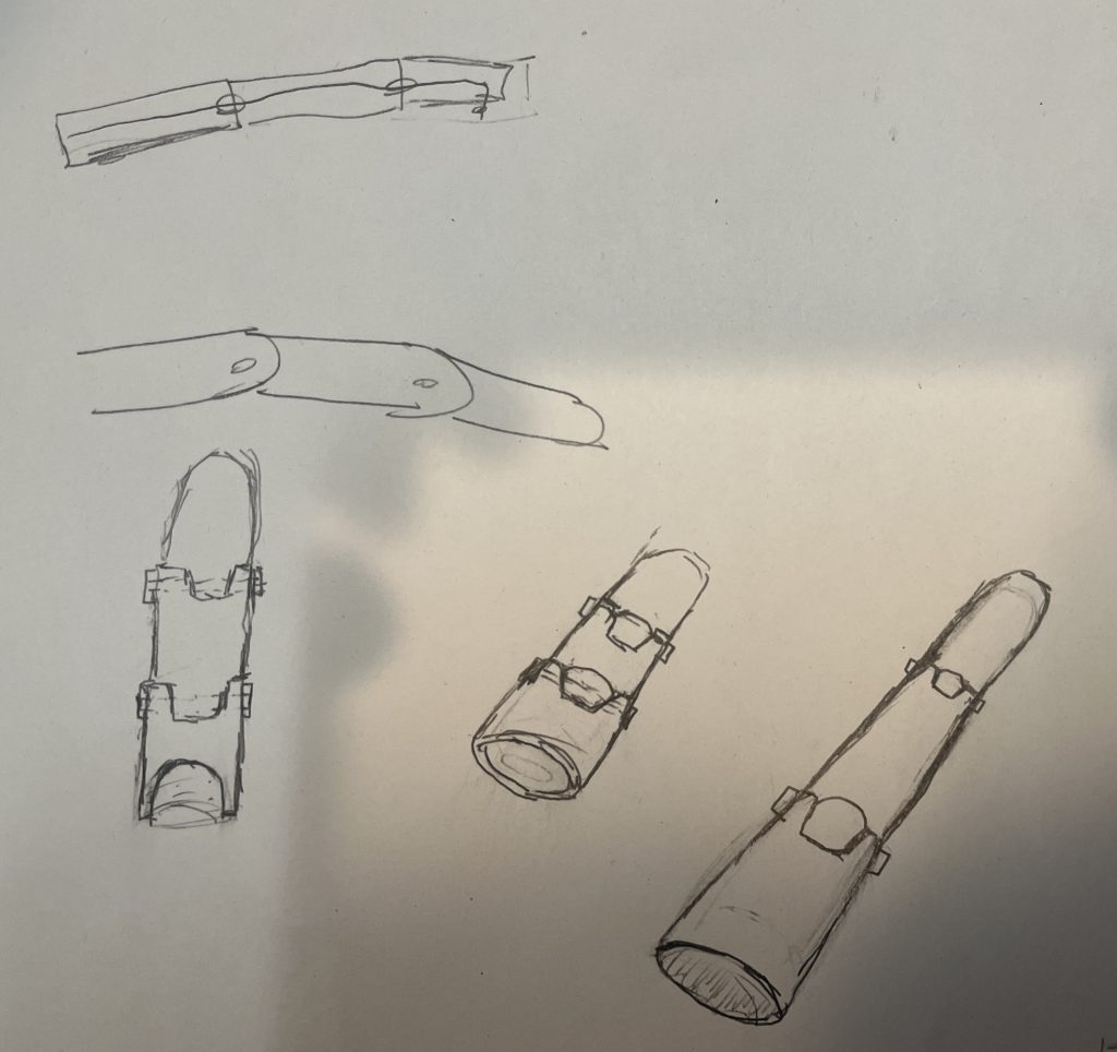
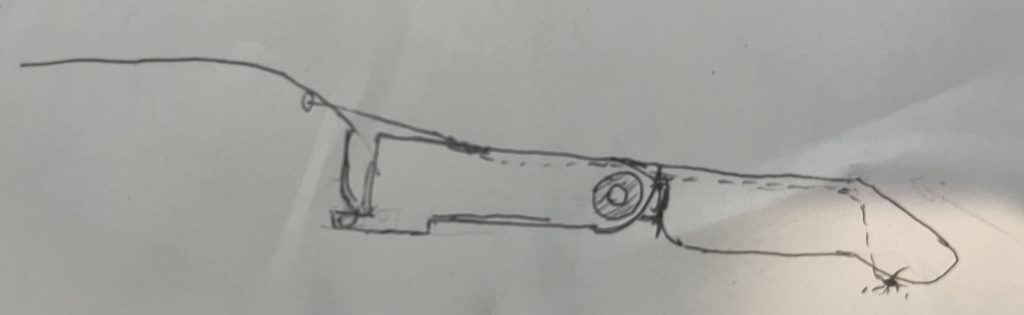
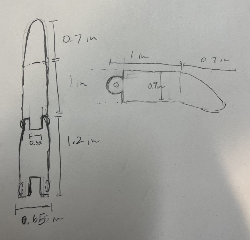
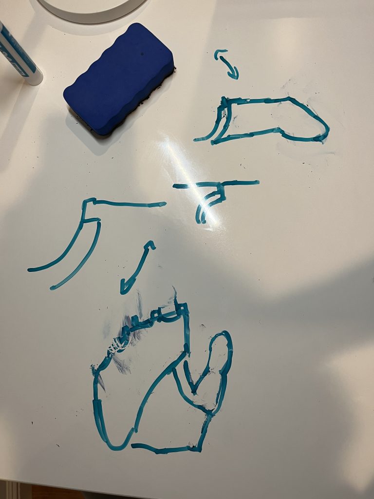
To start my design process, I started with drawing some sketches of what I wanted my device to look like:
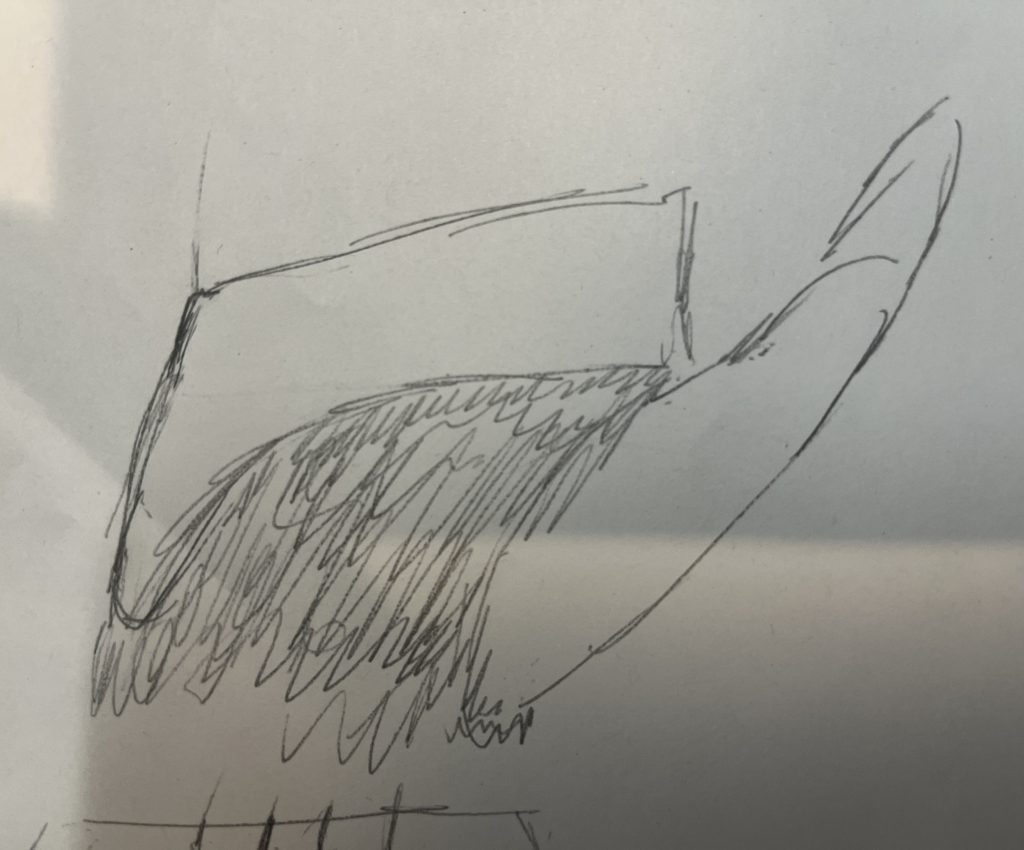
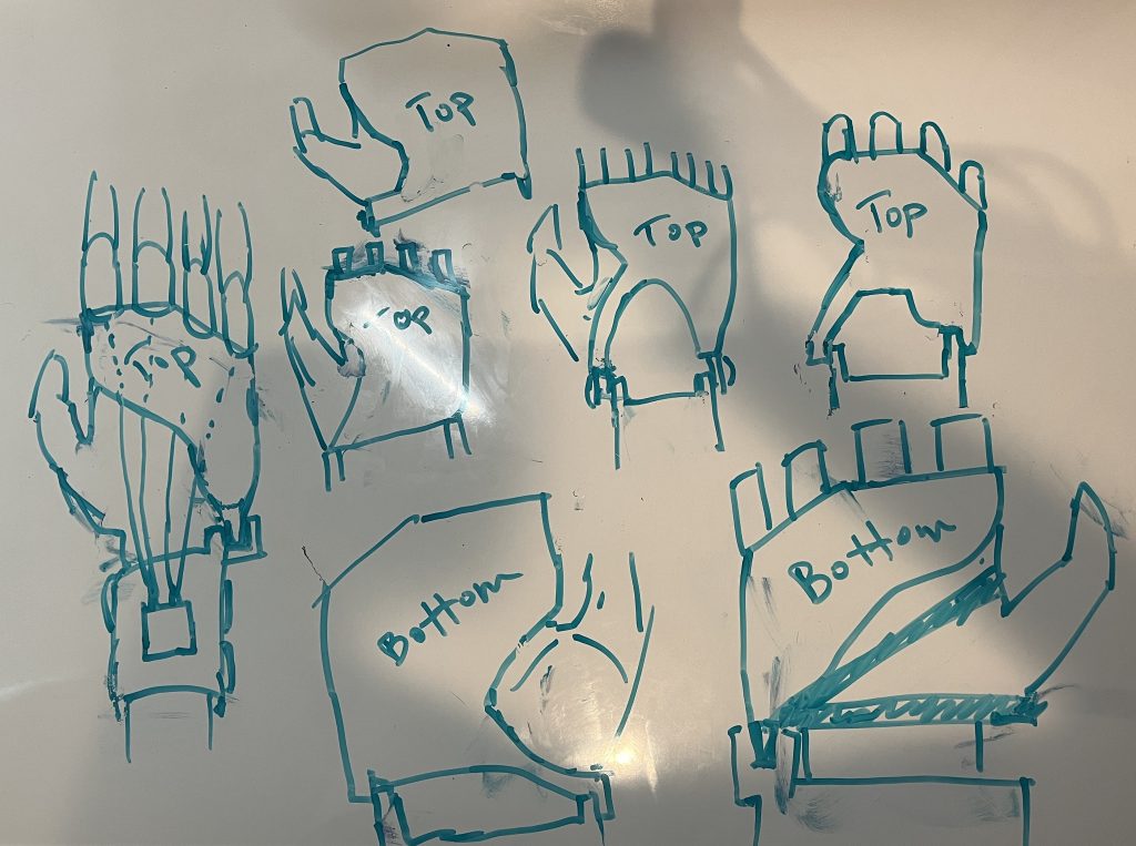
After lots of brainstorming of the fingers, I started to make some designs of the shell for the hand, looking at both top and bottom views that would best fit the hand shape and leave enough room for the thumb to move.
3D Modeling + Testing
Finger Design
After picking a couple designs to develop more, I used Fusion 360 to model them in 3D. But this was by far the most difficult part of my design process because of how many tools I had to learn. Starting as a somewhat experienced beginner, I had to really understand Fusion’s workflow: creating sketches and constraining them, turning these sketches into 3D objects, manipulating the 3D objects to my liking, rinse and repeat.
I started with designing the fingers, which I planned to make two versions: index + middle and ring + pinky.


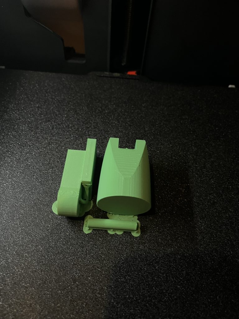
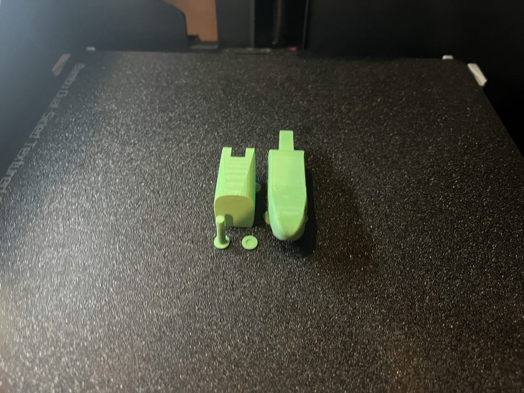
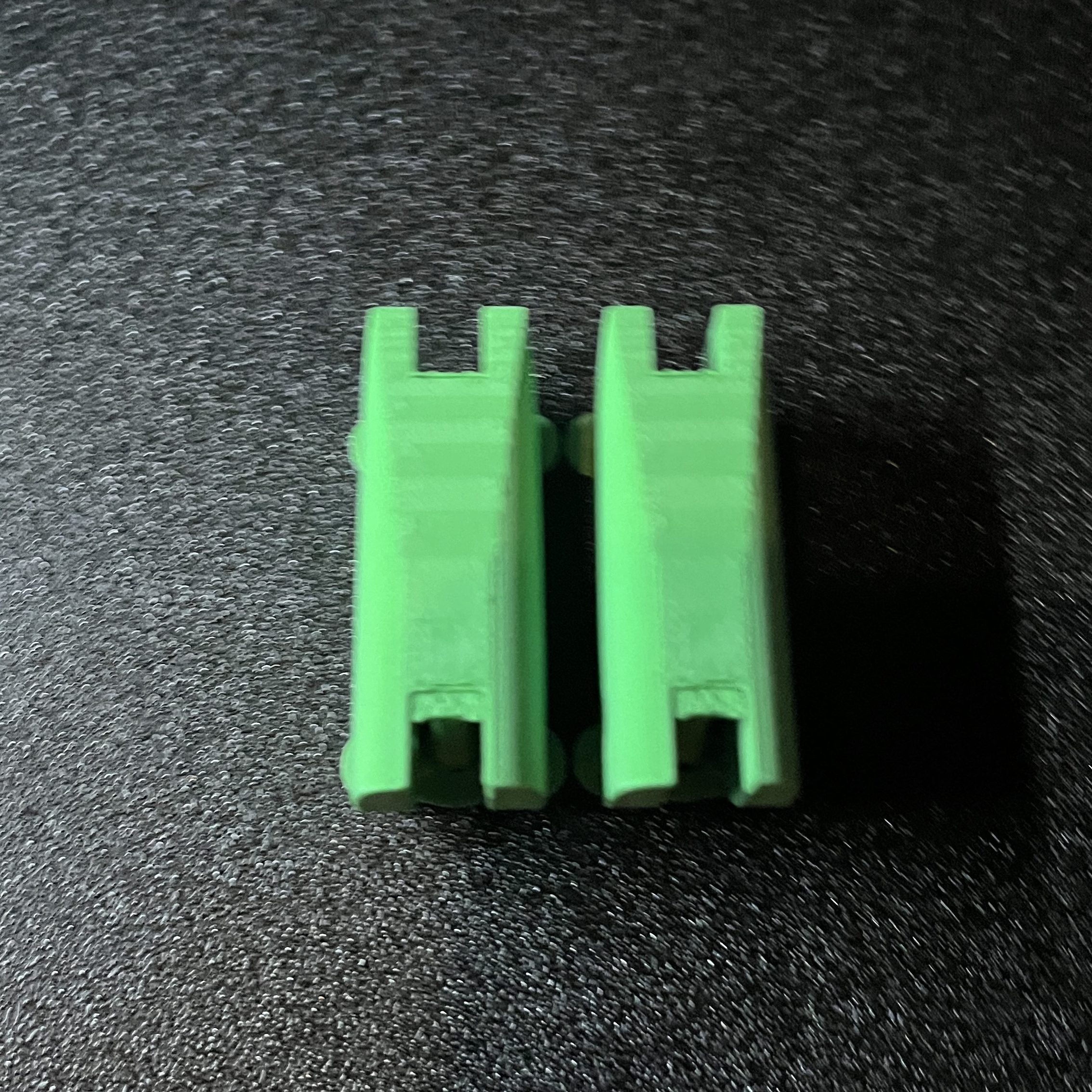
I based this design on the idea that my fingers were to be hollow to allow for parts of fingers that were not functional to fit into the hand. But my dimensions were off and I had the finger base too thick. However, I did make the joint well, as it was able to rotate freely without the two pieces colliding and at the same time stopping the joint from extending beyond horizontally straight. I printed it to test its rotation and check size:
Deciding to throw away the hollow finger concept because it was too big to feasibly fit on a hand and a multitude of over complexities, I simplified my design with much better fit dimensions:


My second version had better dimensions, but I could tell I lost something from the original design that made the finger not work as well. When testing range of motion for the joint, I could barely rotate it 60 degrees before the two finger pieces contacted and this was very far from ideal. The change of dimensions caused the joint to not rotate properly and for there to not be enough space to cut off more material from the finger pieces. The top of the fingers also looked a little odd, as it looked a little thin and weirdly cut off. Seeing I wouldn’t get very far with this design, I started fresh with a third design and attempted to repeat the steps from my first finger design but scaling the change in x and y respectively by the same amount for every line in the first few sketches. This went much smoother and looked much better:


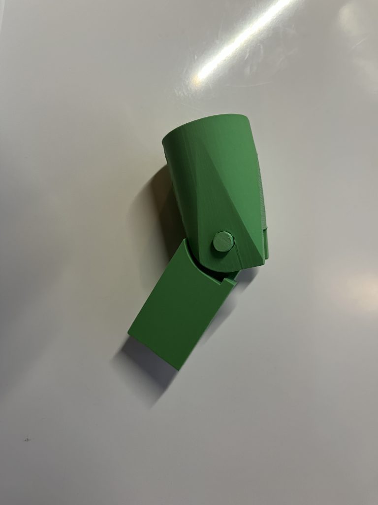
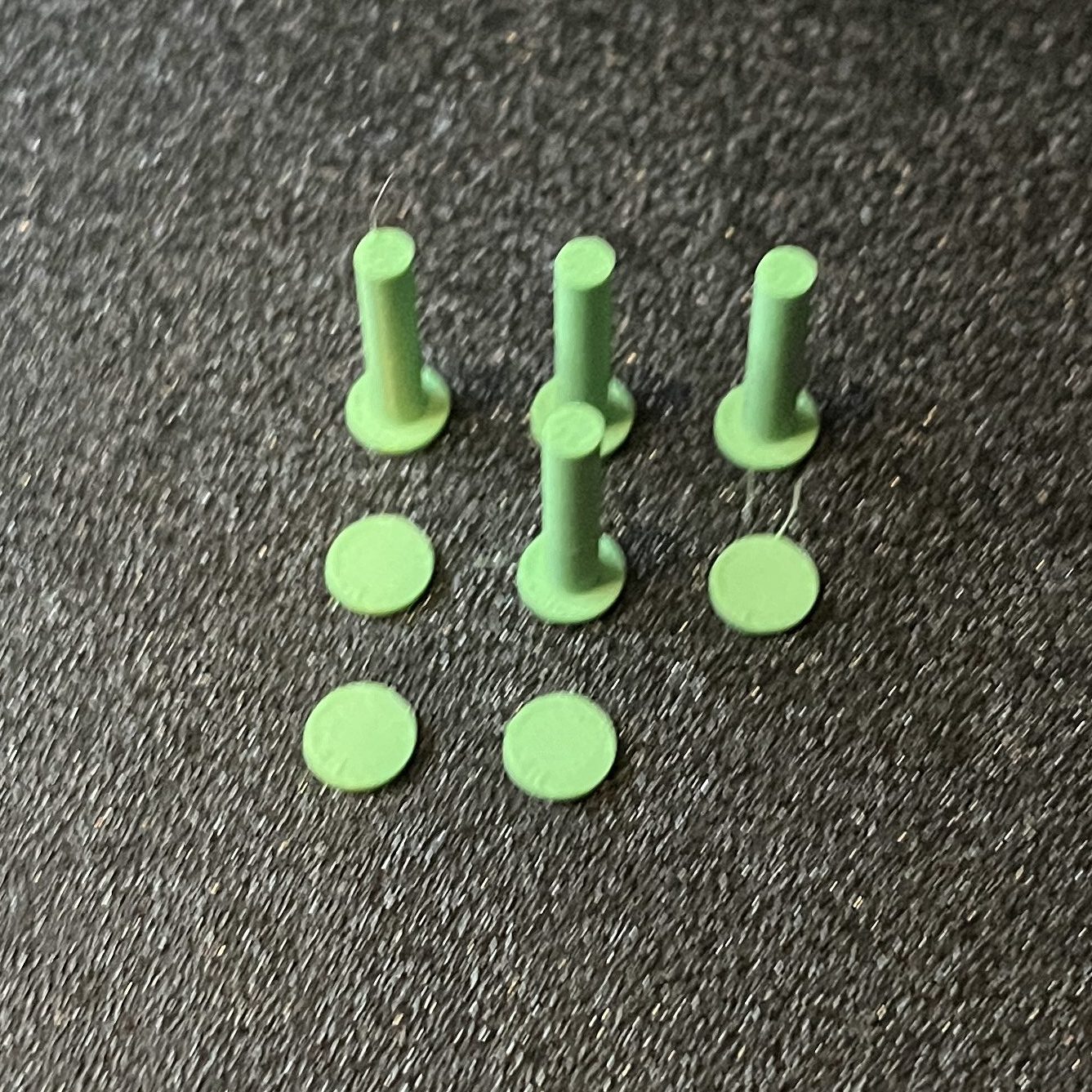
This time there was no weird cutoffs and the finger looked much smoother and simple. After some modification and filleting (turning sharp corners into curved edges), I was able to get the finger to rotate 90 degrees, which is what I was looking for. These photos are from a later modification of dimensions, so the sizing in the screenshots aren’t accurate to this spot in the design process, but it shows what the parts were shaped like. I printed these pieces to test my tolerances (distances between components), joint movement and sizing:
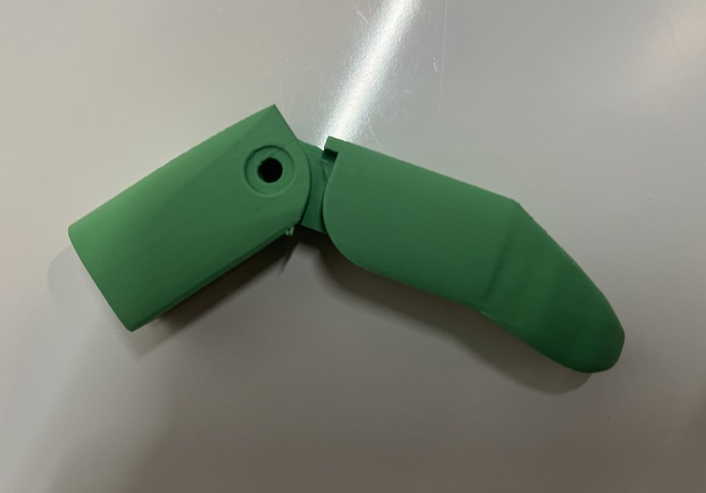
Although the joint worked well, the base piece was very small compared to the top pieces, so the finger was very lopsided. I had to readjust my sketches and their dimensions to move the joint point higher. After fixing some small errors, I added a second hole for the joint that would connect to the hand piece and created a small connector piece that would eventually be combined with the hand. This is the final iteration of my finger:


Hand Design
The design of the palm piece took me the longest of any part of this project. To get a very uniquely curved shape that is smooth, has thickness but also hollow inside with certain faces open was incredibly difficult to figure out. After significant research and trial and error, I went through four different design methods in Fusion 360: solid modeling, 2D form sculpting, 3D form sculpting, and surface modeling.
I first started with taken pictures of from different angles as reference for the hand shape and imported them into Fusion as canvases:


I started to make sketches using these images and came up with a structure for the hand:


I tried form these sketches into something with solids using the “Loft” command, but the shape always looked extremely warped and I could not constrain it how I wanted to to fit a certain outline/rail. I also couldn’t empty the middle once I had a solid body. I also thought the images I had were a little hard to use. Although they worked for some time, I realized that because my fingers were spread apart differently, I should start fresh with new pictures that were more similar in size and hand positioning. I created my sketches again and this time lofted each individual curve together to form a series of solid bodies that could be joined together:


This looked even worse than the last model, with no smoothness, a flat and discombobulated front part and weird looking lofts. Starting to become a little discouraged, I went back to the drawing board and did more research on various modeling techniques that could give me my desired result. I came across form modeling and decided to give it a try. Instead of directing using the sketches with commands, I would use them as reference to pull/push faces, points and edges on a form get a general shape that would match the sketch model.


At first I thought this would work, as my form looked good and matched my sketches. But I would soon come to realize how imprecise form modeling like this was. I had no way to make very flat faces, shell out the inside or join it with other components effectively. After more research, I started fresh with surface modeling. I used the surface version of the “Loft” command, this time bridging my curves with a surface of no thickness. This in theory would allow me to thicken it later and control how much space I have on the inside of the hand. But like the solid lofting, it gave me weird results, especially when I lofted from the first curve to the last point at the very front of the hand. It was unusable, but I kept trying and attempted to make individual lofts for a couple curves at a time, and lofted the top and the bottom of the hand individually to join them later. This became more of a mess than what it was worth:


No matter what I did, even trying to patch together surfaces in weird ways and then combining solid bodies later and comprising on having a curved front, nothing worked. I had errors, warping/distorted surfaces and nonfunctional solid bodies from those surfaces. Completely stuck, I had no clue what to do, but I thought back to form modeling and how it got the closest to what I was looking for. I had only started with a fully solid form body and manipulated it from there, instead of starting with flat planes and thickening them later to get the hollow inside I was looking for. Realizing my mistake and starting on a new file for the fourth time, I had began bridging and extruding planes, slowly building out the shell of the shape. My first attempt started well, but I didn’t think the sketch model I had worked well because the front was taller than the back, which doesn’t really match the shape of an actual hand.


Usually the hand is the tallest at the base of the palm/wrist and starts to taper off towards the fingers. I created a new sketch model making these changes:


Starting the form modeling process anew, I slowly outlined the hand on the side and top, built out the outside into a rough shape, and then went back in and adjusted all my faces and points with finer detail to get the shape I wanted. But I used one of the designs I had chosen earlier, with a big hole for the thumb and a piece wrapping below the palm to keep the shell in place on the hand (it would otherwise slide off). This is the form I ended up with:


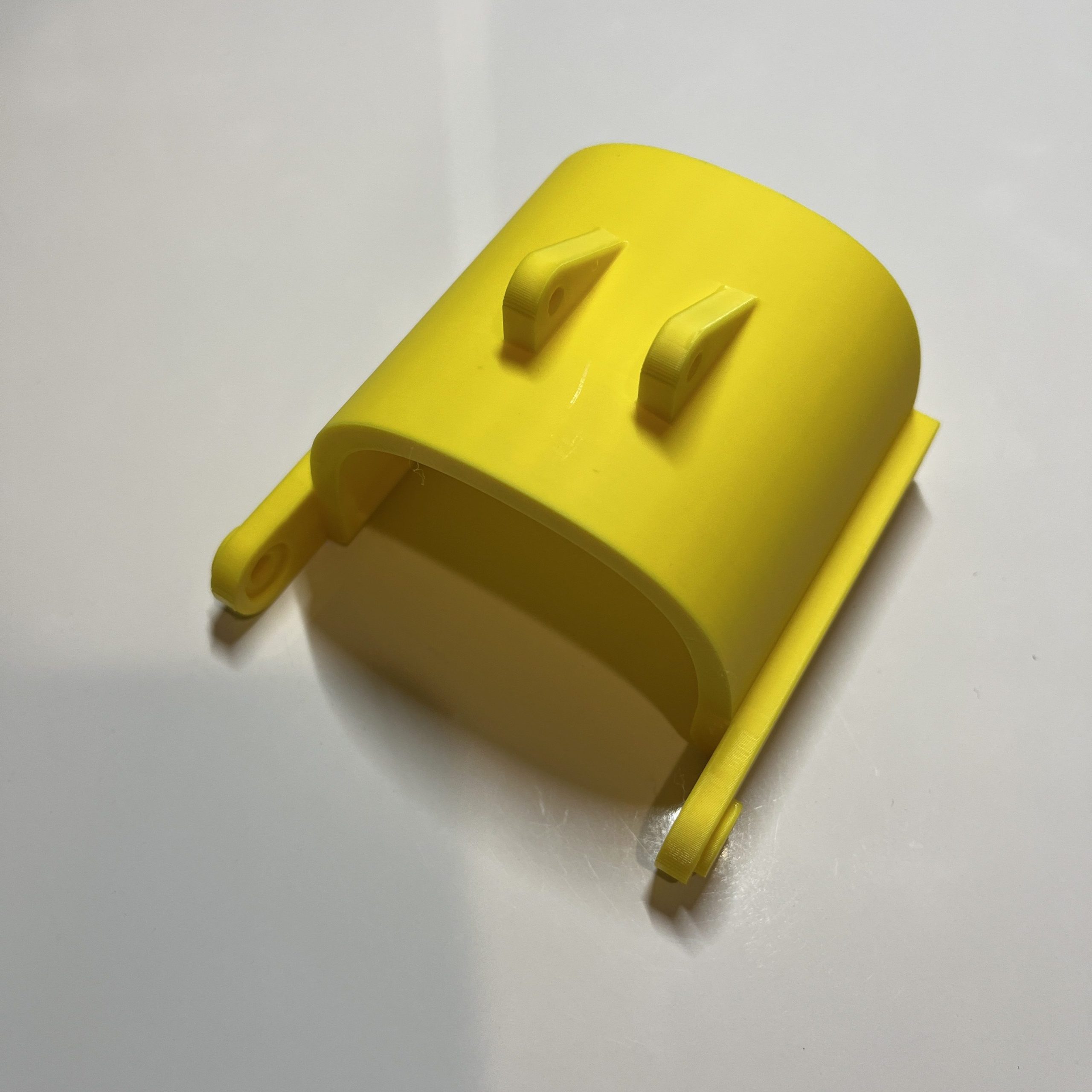
Happy with the shape, I thickened it to 0.2 inches and added pieces on the back of the shell to fit a joint for the wrist guard, the part that holds the hand in place and actuates finger movement:

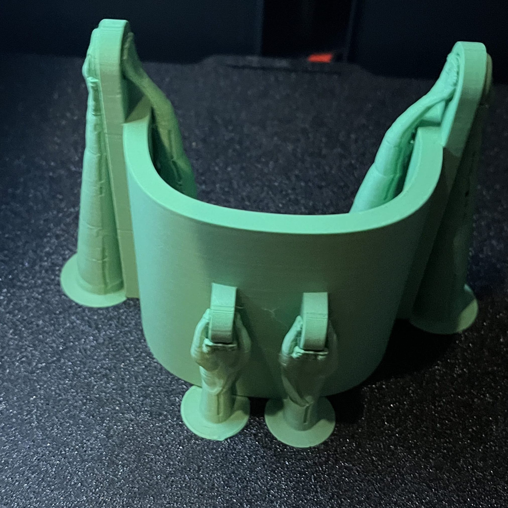
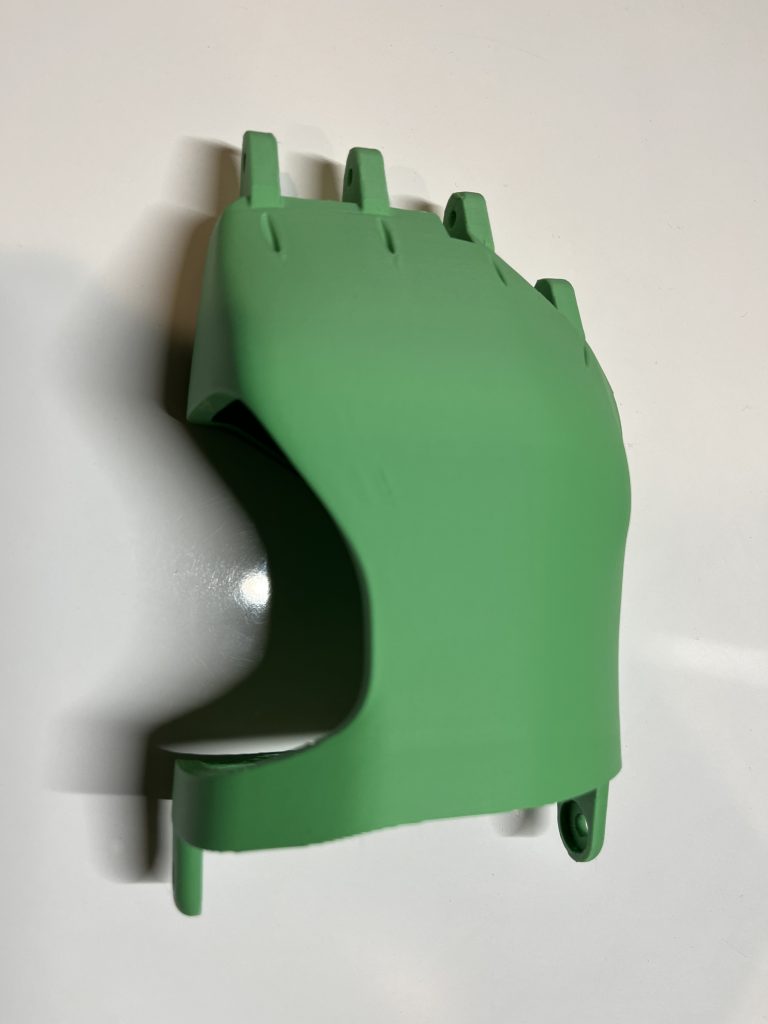
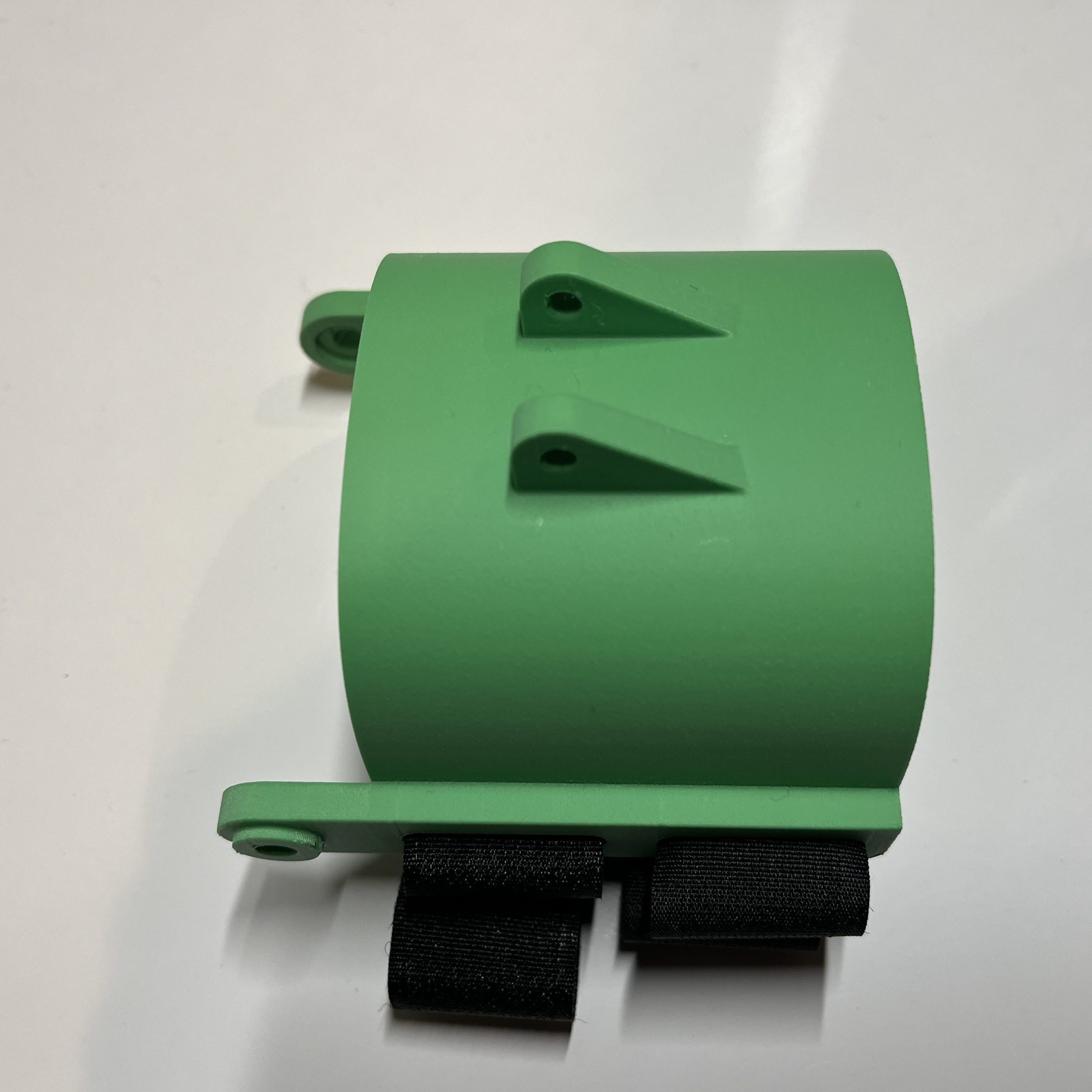
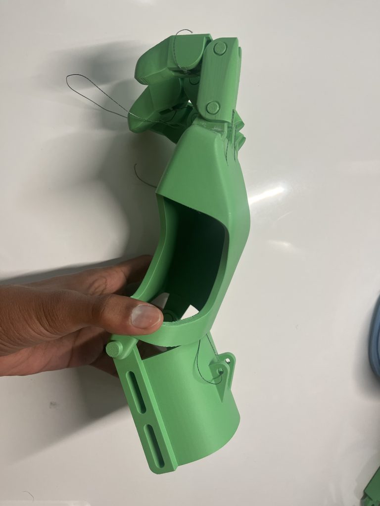
I then started the design of the wrist guard. For this design, the goal was to have something that could hold the wrist in place and provide a slot for strings to attach in order to move the fingers. Below is my final design:


The hand and wrist slot together like this:

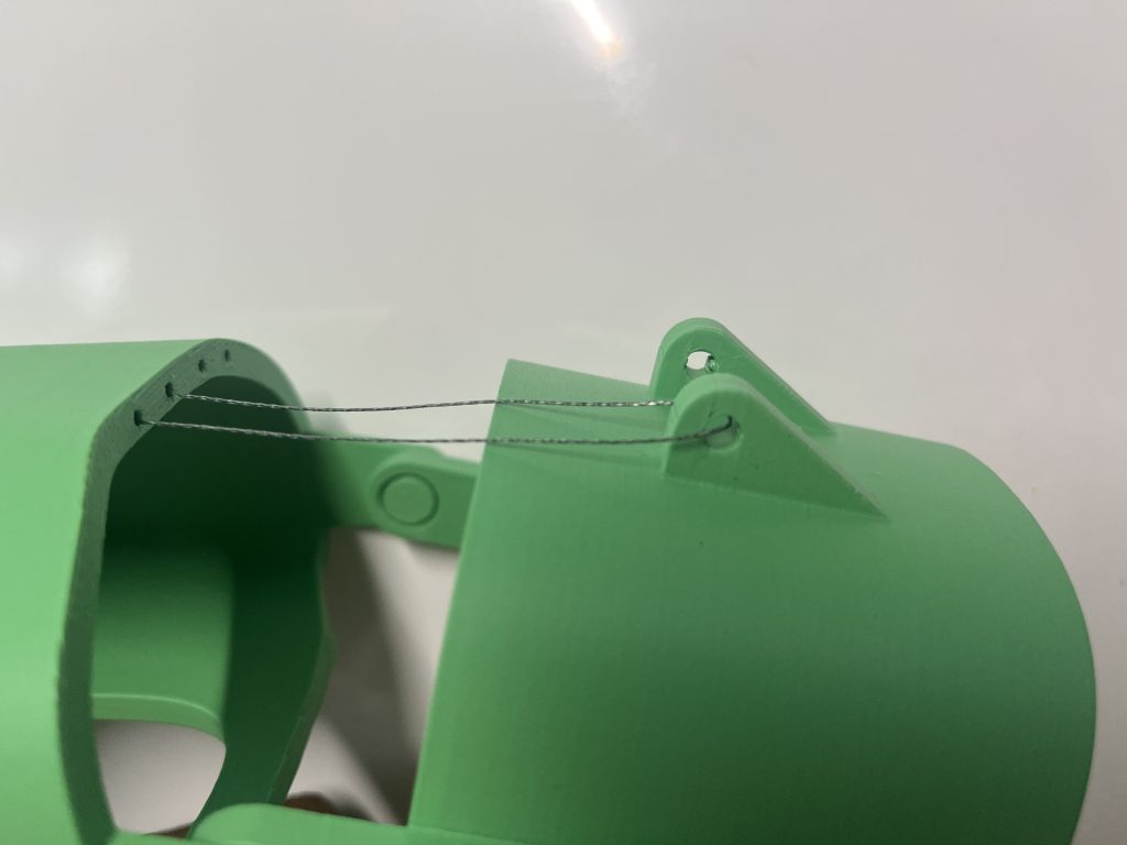
The last part of finishing my design was incorporating the fingers into the shell. I had a lot of trouble figuring out the best way to do this, but eventually decided to just cut out parts of the hand shell that overlapped with the fingers. I also made small holes for the strings that ran from the finger area to the back edge of the shell. Below is my final (at the time) design:


Fabrication (Part 1)
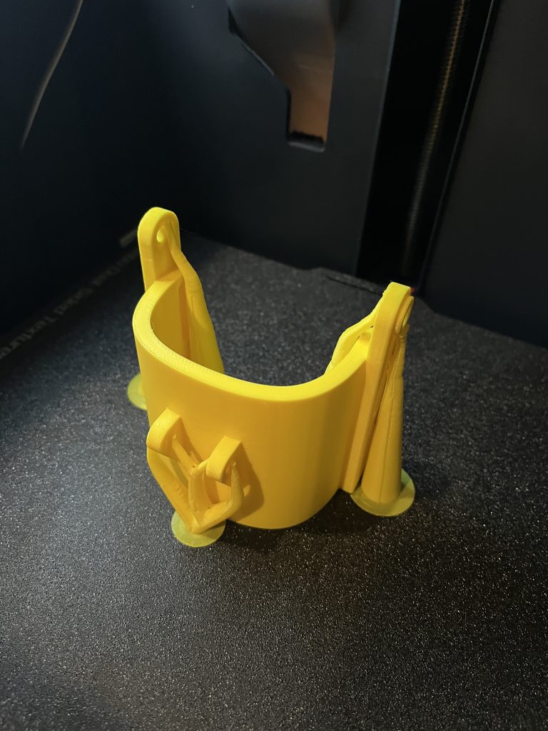
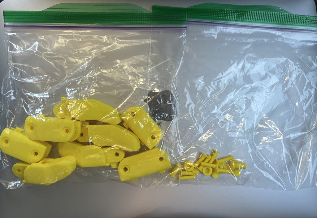
Once my design was complete, I started printing all my components. I started with the wrist guard. Each component for this build was printed at a 0.16mm resolution at 15% infill using a Bambu Lab P1P (with an enclosure).
After printing all my pieces, I started the assembly process:
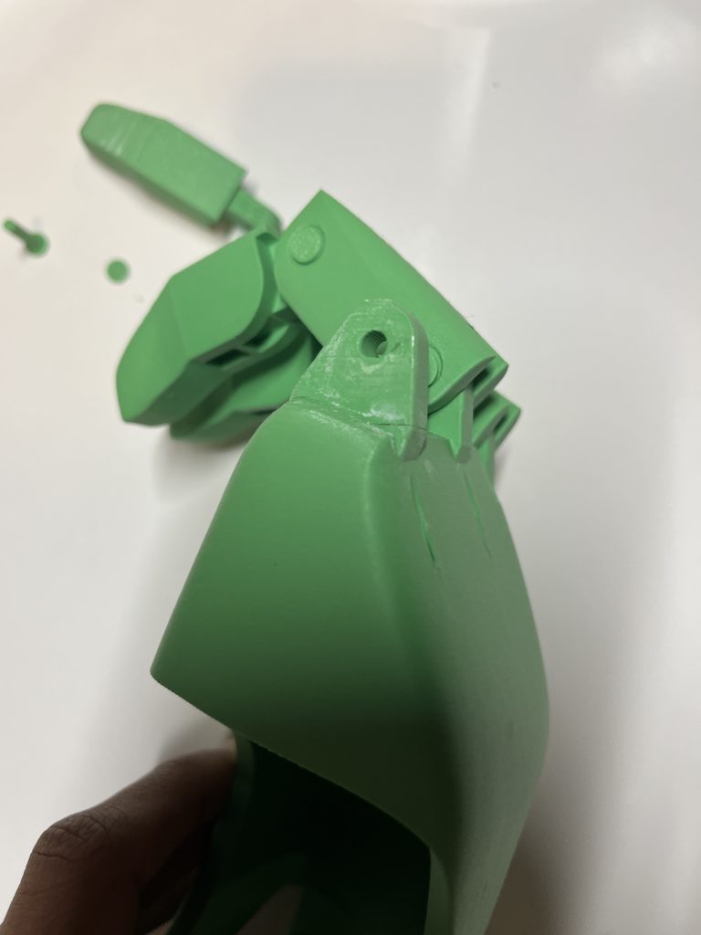
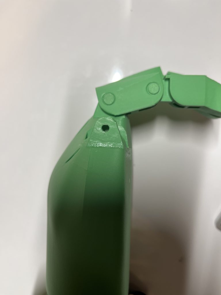
During the process of gluing together my components, some of the print layers started to separate at the base of the finger connectors from the hand to the base of finger on two areas. I glued them back together, filling any cracks, but there was visibly a small separation. I don’t know what caused this issue, but it is important to remember for future prints that could be compromised in that area.
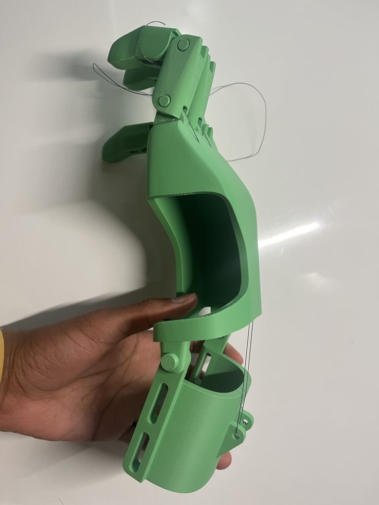
I finally finished assembling the fingers and started the process of stringing each finger to the wrist guard:
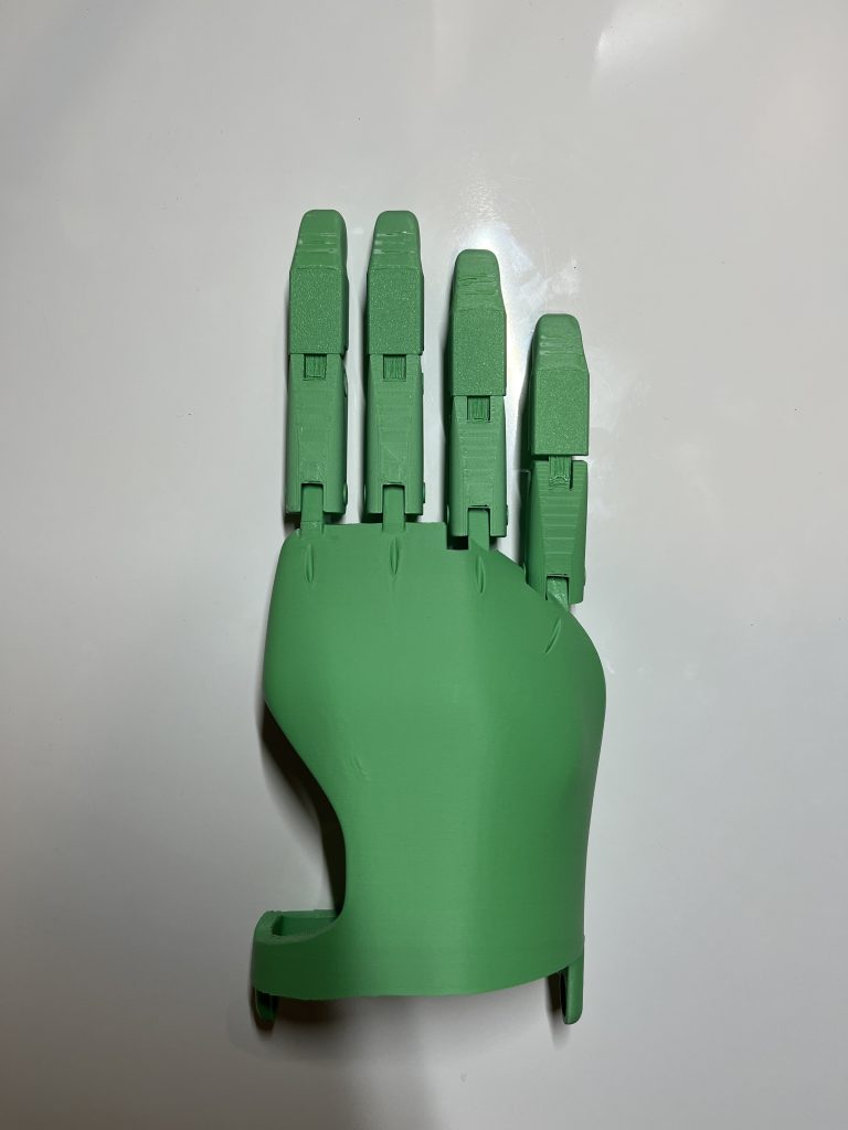
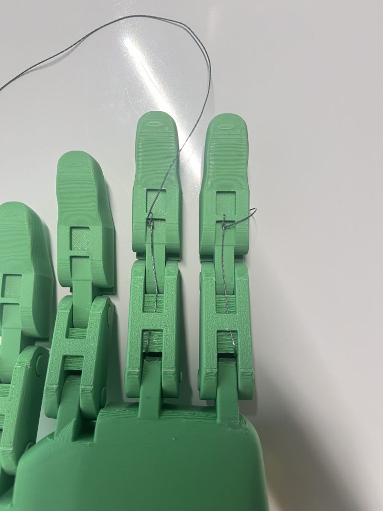
After stringing the first two fingers, I realized a couple of huge mistakes I made. When designing the hand, I had overlooked how the finger would actuate with the strings, and the fact that when the wrist would move, the string would pull itself towards the base finger segment instead of the hand shell kept the finger locked in place and unusable. Additionally, there was no tension keeping the fingers straight when the wrist was at its rest position, so they were just limp. My design was fundamentally nonfunctional, and this was extremely disappointing because of all the designing, testing and printing I did to get to what I thought was my final device model.
Redesign
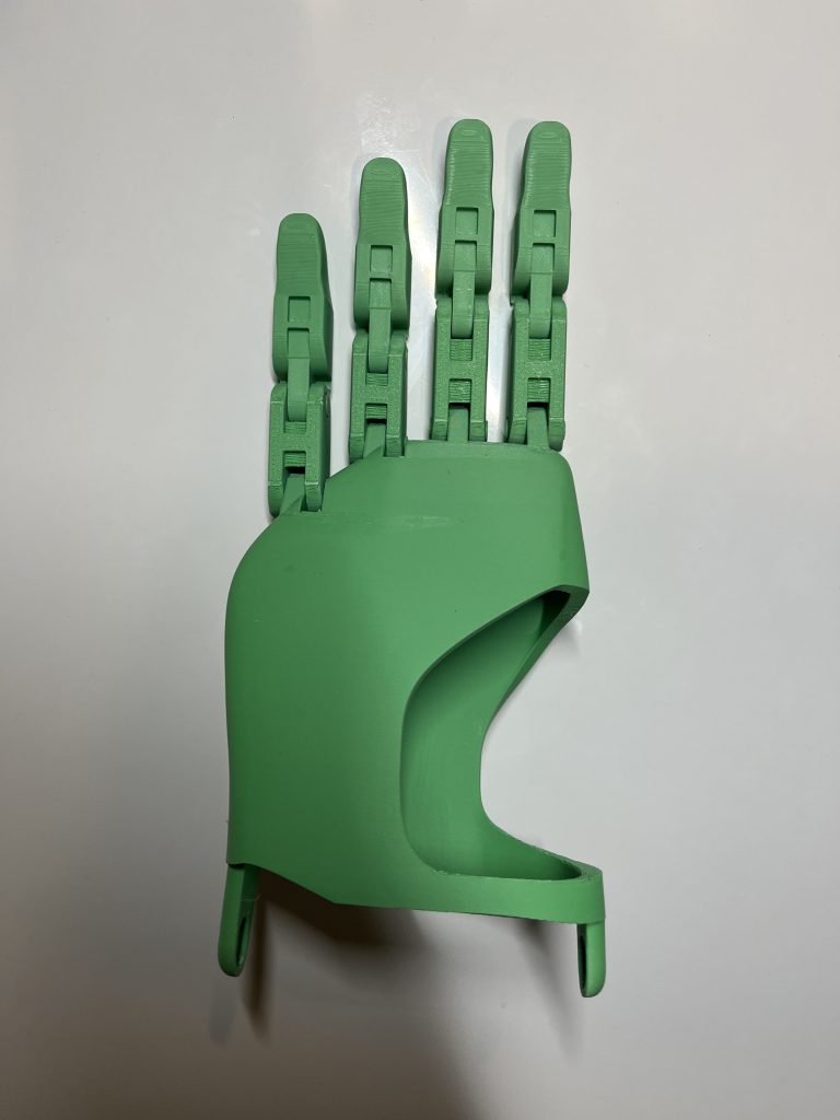
After reviewing changes I needed to make, I decided to keep my current design and modify it where I could to simplify the changes as much as possible. For starters, I made holes in the hand shell behind each connector for the fingers, which would in turn pull the finger to the hand when actuated rather than pulling the finger into itself.


To fix the tension problem, I decided to use dental elastics (very small rubber bands) that would hook onto slots on each finger joint. I designed these finger joints to also to be nearly touching when the fingers are straight so they don’t overextend past straight horizontally.


Because all the fingers share the same second segment I only had to design the slot once for that piece, and designed slots for the long and short base finger segments as well (that’s why it looks like something is missing but everything is good).
Fabrication (Part 2)
With my new changes, I began printing and assembly a second time.
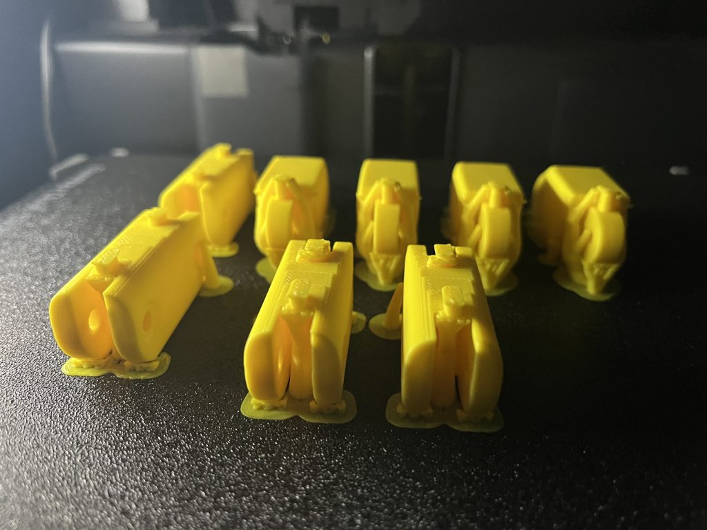
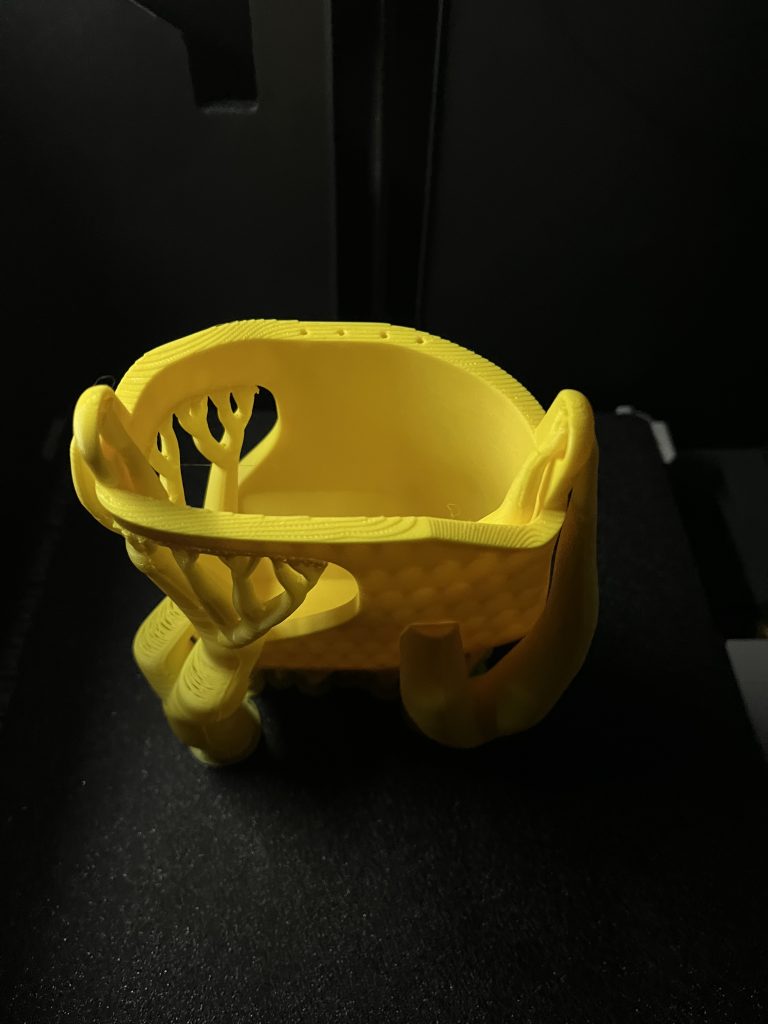
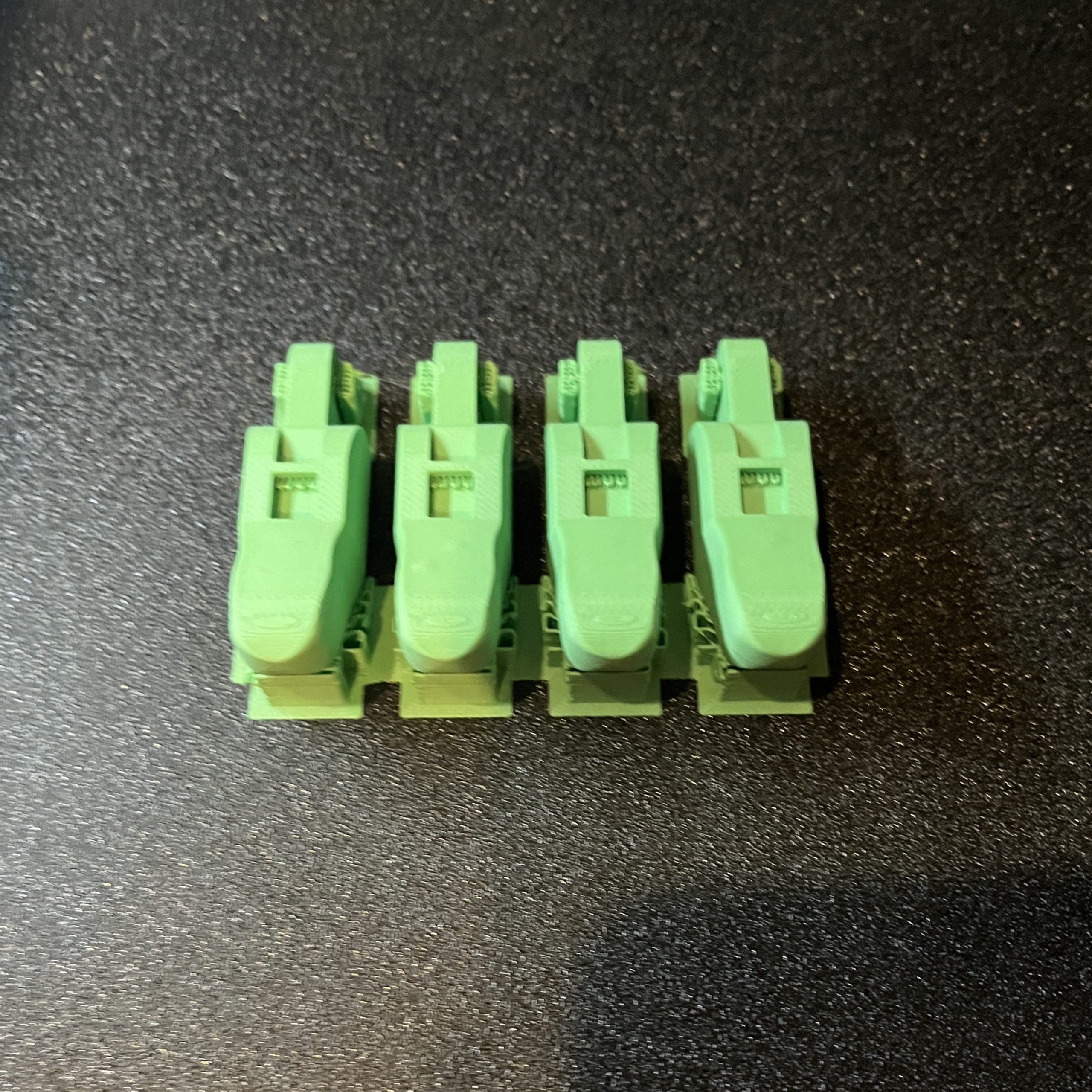
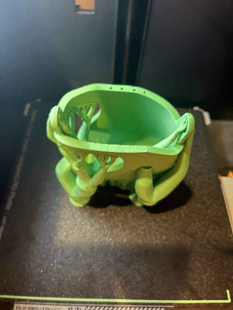
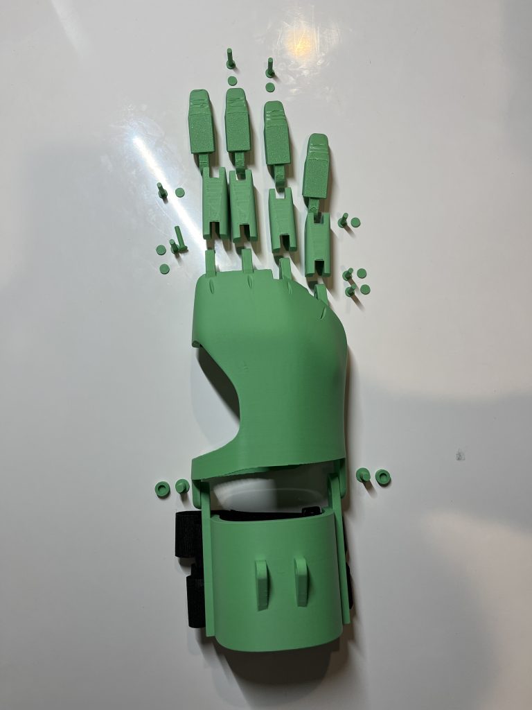
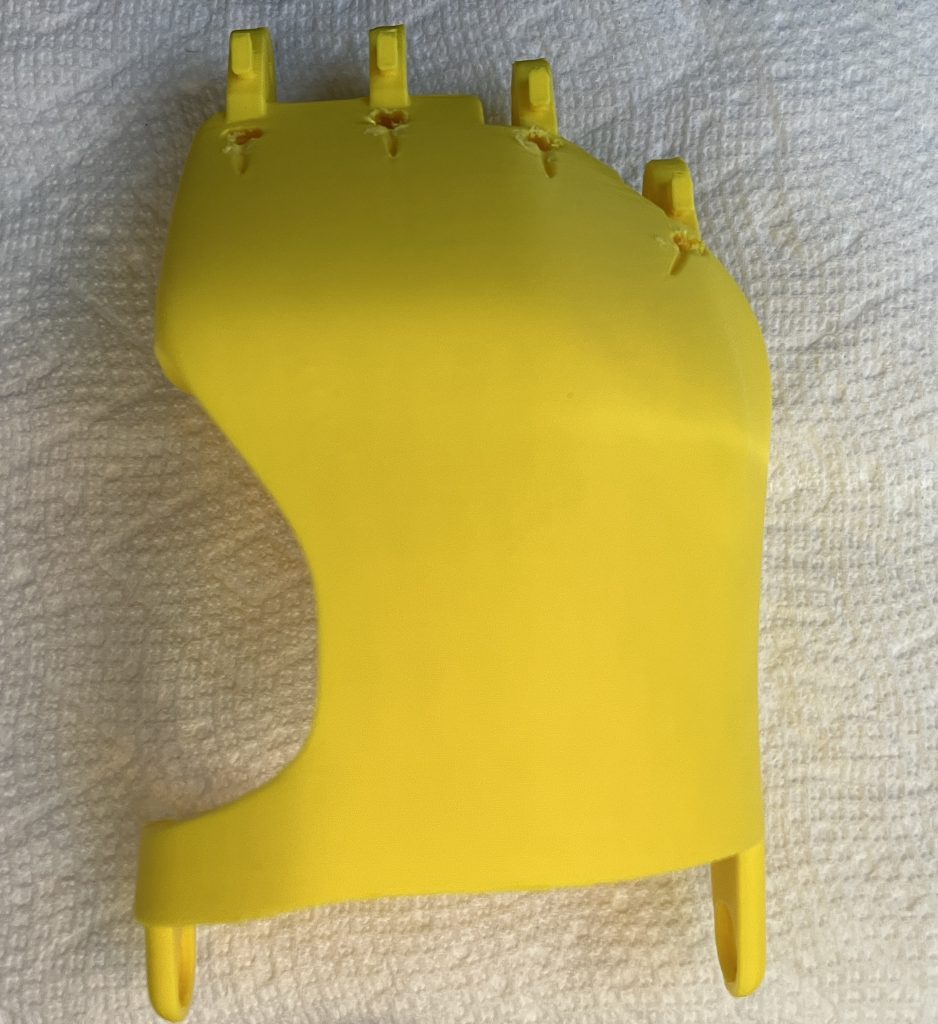
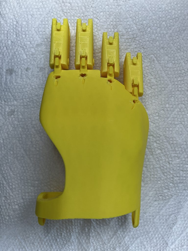
After removing supports, this is what the parts looked like:
These are some of the stages of assembly:
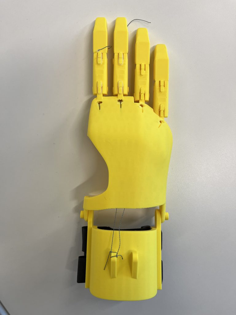
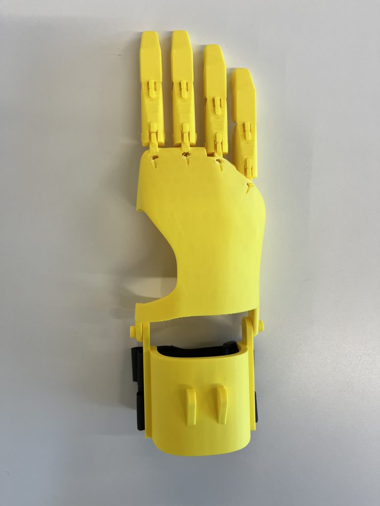
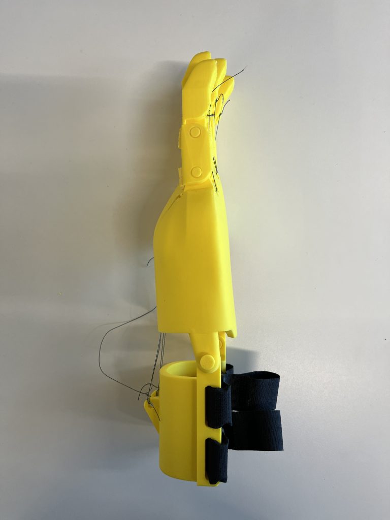
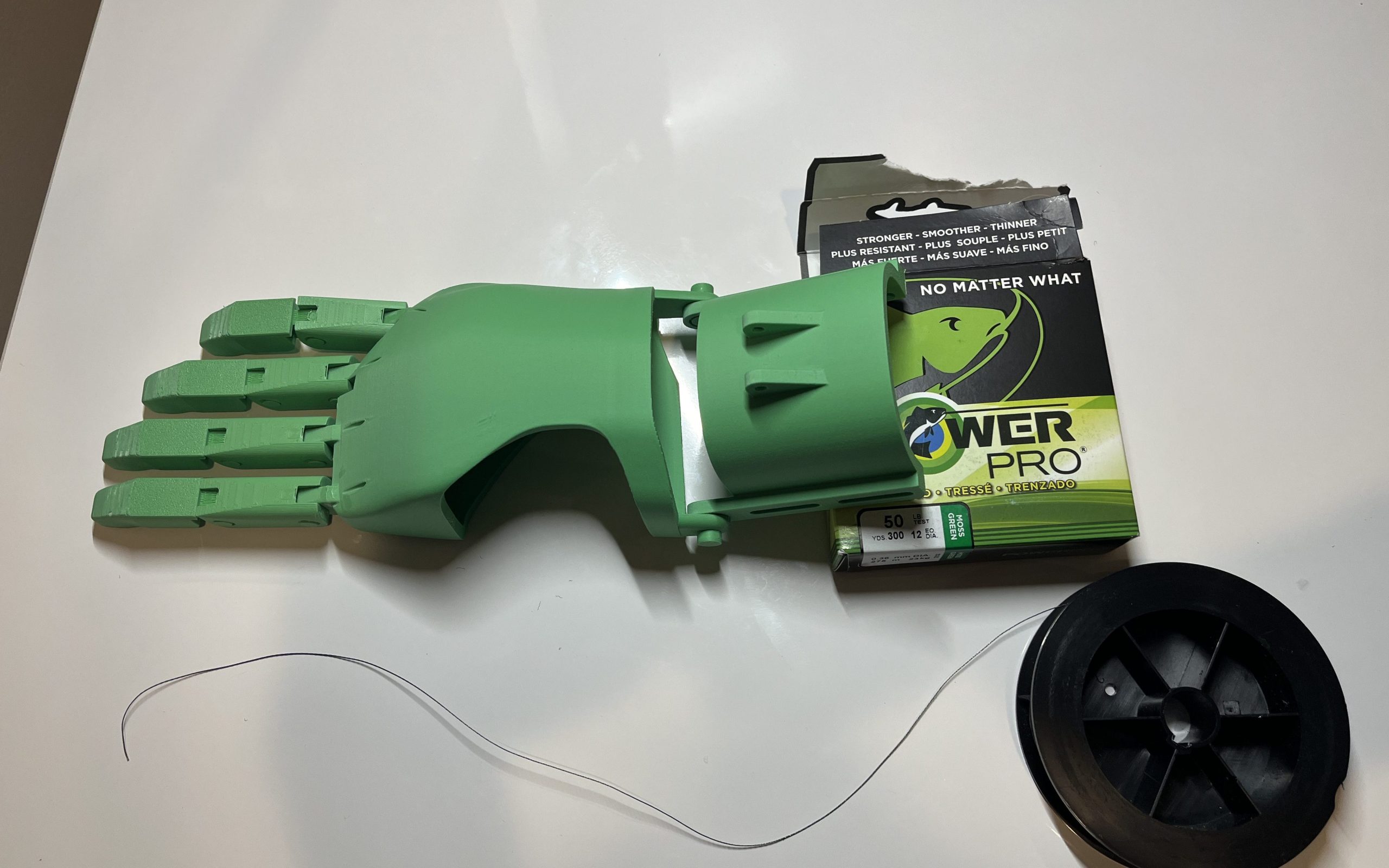
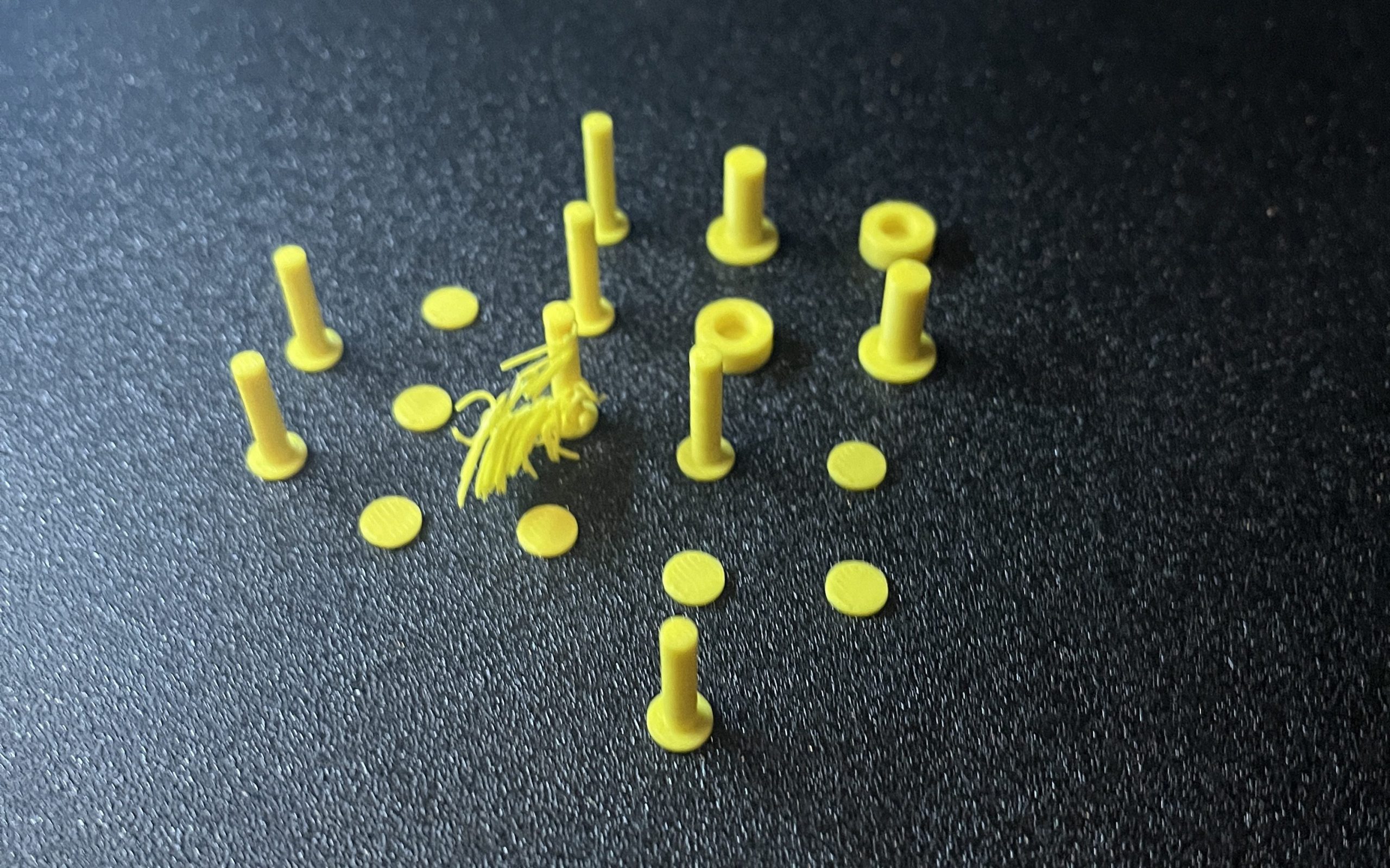
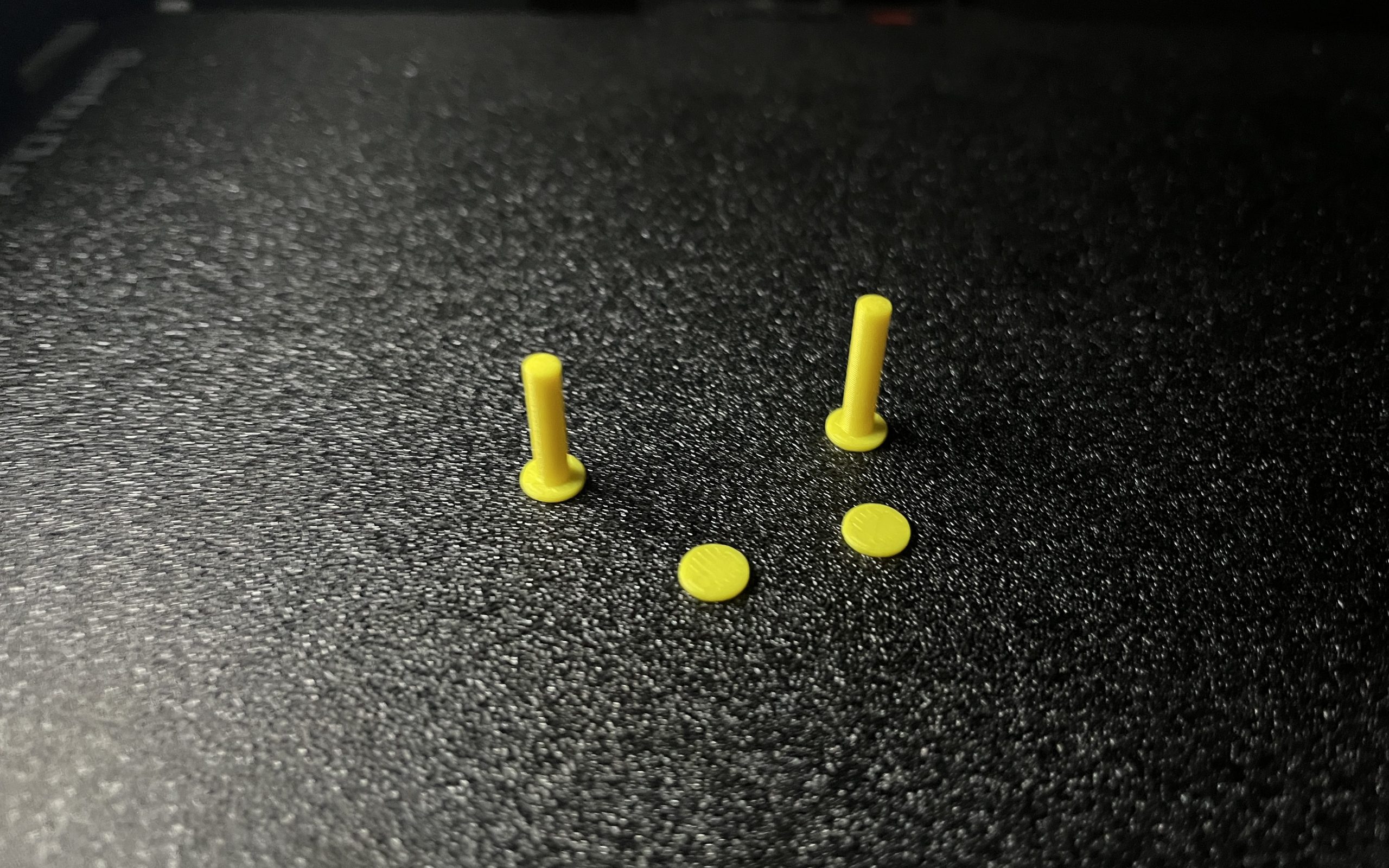
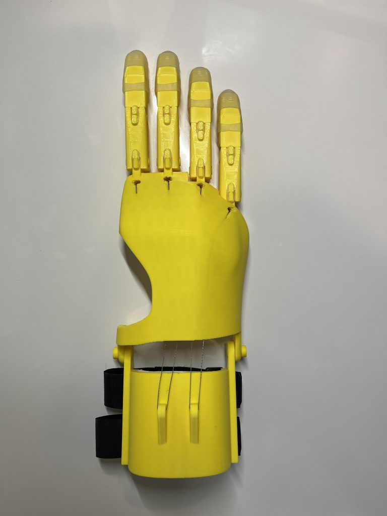
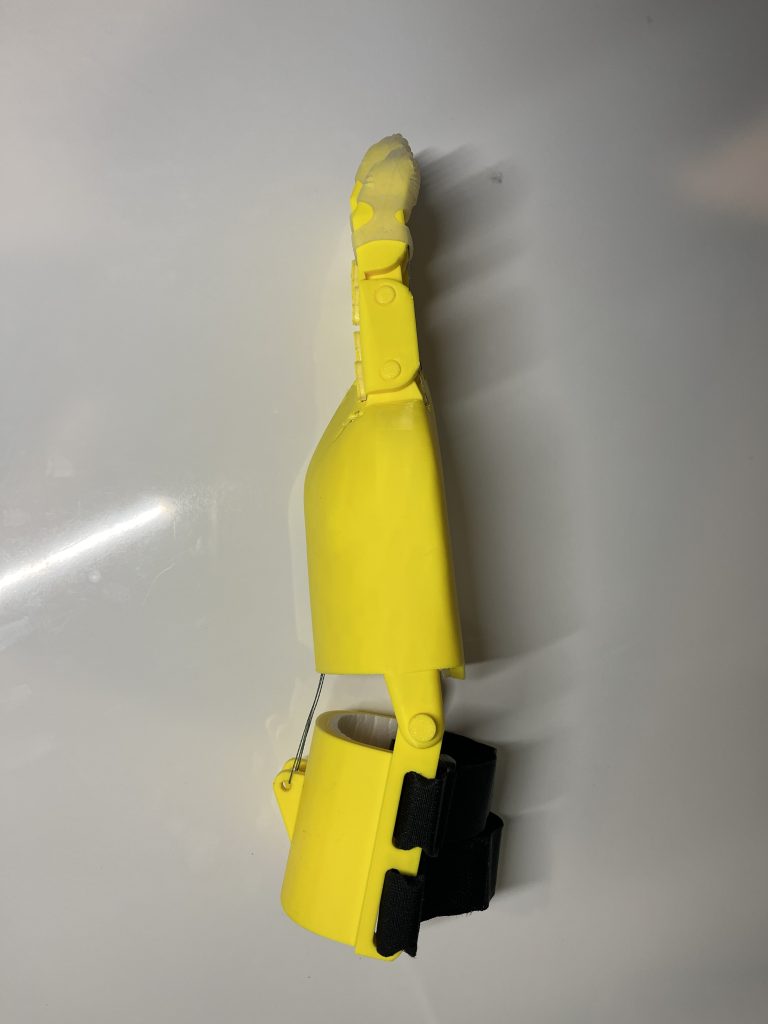
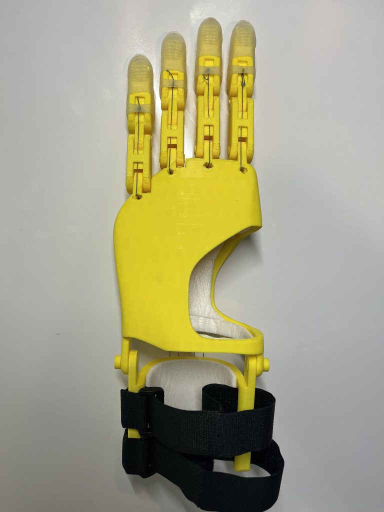
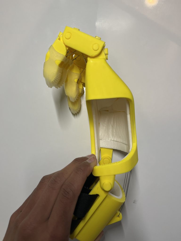
With stringing done, I added some foam padding on the inside of the wrist and hand shell for more comfort and some rubber finger tips for better grip. Here are the pictures of my final hand!
Reflection
This project was successful and I came out of it with many new skills and ideas. My hand evolved a lot from the first design, but that is just what the design process is about and the hand is fully functional. But there are some things I could have done differently.
- Assembly – parts could have been designed to better fit without needing extensive gluing or the axles for joint rotation could have been made snap fit to require no glue
- Design techniques – if I had even more time, I could have figured out a way to better model the unique curves of the hand shell and find a way to make the process more precise and simple. Maybe I could have contacted people at e-NABLE with more experience using Fusion 360 and got their input on how certain hands were designed (Phoenix Hand v3, Unlimbited Arm and more).
- Testing – I could have done more testing of individual parts of the hand before putting the whole thing together, which would have saved me some time, printing material and supplies
Outside of these things, I would say my design went smoothly and I will continue to improve my design skills and understand of prosthetics with future projects.